SRT X-BAND RADAR SYSTEMS
DESCRIPTION AND MAIN CHARACTERISTICS
304202P003 1.8 Rev. C
1.3.2.2 SRT Electronics parts
The SRT X-BAND RADAR Pedestal contains high speed electronic circuits,
which allow to the RF HEAD, transmission, reception and processing the RF
echoes.
Table 1.3.2 – SRT X-Band 12 and 25kW Composition lists the main
assemblies composing the unit and their position inside the unit.
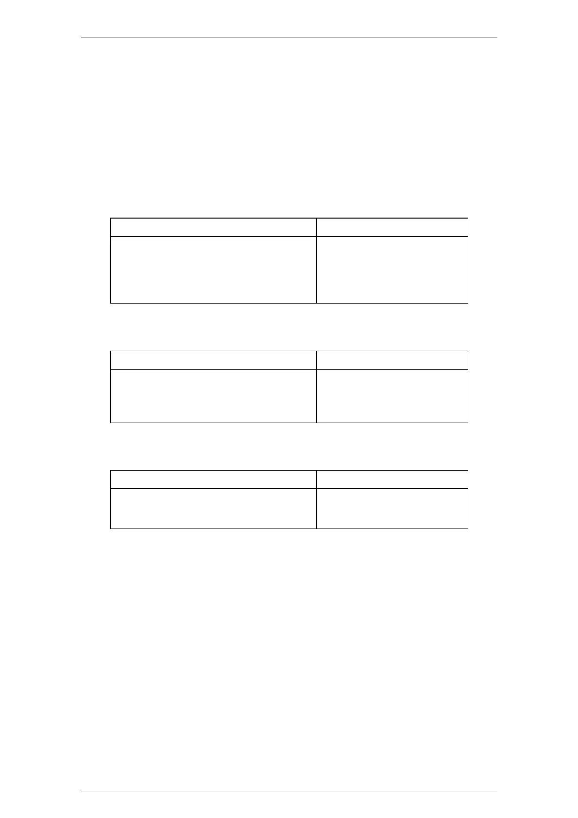
Table 1.3.2 – SRT X-Band 12 and 25kW Composition
DESCRIPTION POSITION
RF HEAD Chapter 9, Figure 9.1.4, pos. 7
Electronic Rack Chapter 9, Figure 9.1.4, pos. 4
Bearing Reader Board Chapter 9, Figure 9.1.30, pos. 2
Brushless motor controller Board Chapter 9, Figure 9.1.4, pos. 5
Brushless motor Chapter 9, Figure 9.1.4, pos. 6
Table 1.3.3 - RF HEAD
DESCRIPTION POSITION
Magnetron Chapter 9, Figure 9.1.27, pos. 2
Circulator Chapter 9, Figure 9.1.27, pos. 3
Limiter Chapter 9, Figure 9.1.27, pos. 4
RF_Amplifier Assy Chapter 9, Figure 9.1.27, pos. 5
Table 1.3.4 - Electronics Rack
DESCRIPTION POSITION
SRT_Control Chapter 9, Figure 9.1.6, pos. 6
SRT_MOS Chapter 9, Figure 9.1.6, pos. 7
SRT_Power Chapter 9, Figure 9.1.6, pos. 8
The Electronics Rack is connected to:
− the Bearing Reader Board Read-out by a connector (Chapter 9, Figure
9.1.17 pos. 2) on the SRT Control Board.
− the Brushless Motor Controller Board (Chapter 9, Figure 9.1.17 pos. 3).
− the RF HEAD (Chapter 9, Figure 9.1.17 pos. 4 and Chapter 9, Figure
9.1.15 pos. 1)
− the Display Unit, through the Main Connector (Chapter 9, Figure 9.1.3
pos. 3).