SRT X-BAND RADAR SYSTEMS
CORRECTIVE MAINTENANCE
304202P003 6.7 Rev. C
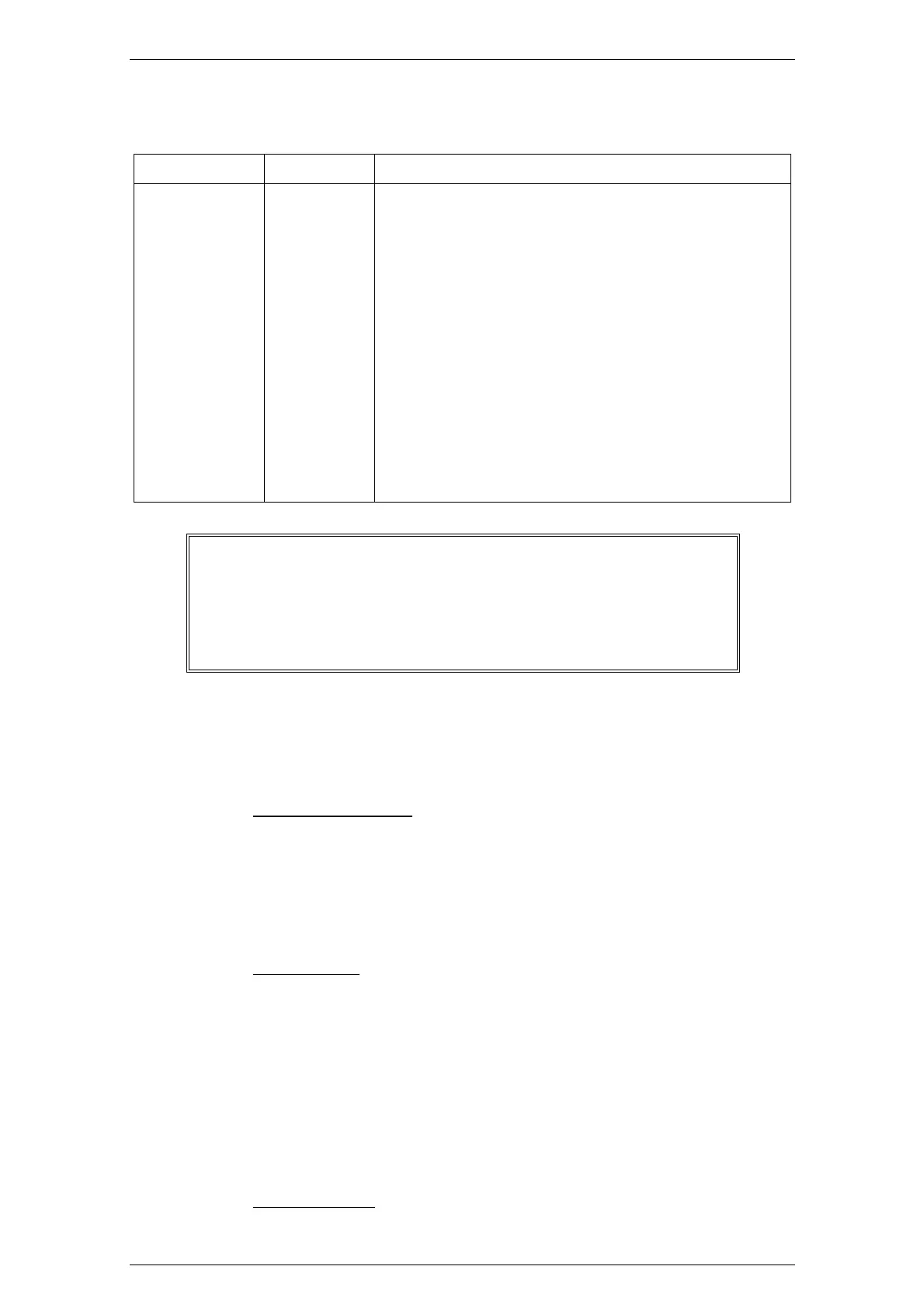
Table 6.2.2 - Connectors of the Electronics Rack
Board Connector Purpose
SRT_Control J4 BNC, Video Signal output
SRT_Control P2 Terminal board for the signal to/from the Display
Unit
SRT_Control TB1 Safety Switch input
SRT_Control J12 Cable for the Optical Read-Out connection
SRT_Control
J1 Small BNC, Video Signal input
SRT_Control
J2 Small BNC, Tune Signal input
SRT_Control
P1 RF_Amplifier controls
SRT_Control TB3 Terminal Board for the Brushless Motor
Controller
SRT_Power TB2 Main Power input
SRT_Mos A – K – Fil Magnetron terminals
WARNING
WHEN THE ELECTRONICS RACK IS INSERTED ON THE
FIXING BOLTS PAY A LOT OF ATTENTION NOT TO DAM-
AGE THE WAVEGUIDE JOINT (Chapter 9, Figure 9.1.31, pos.
1)
6.2.9 Replacement of the Bearing Reader
Board
a) Required Tools
− Set of screwdrivers,
− Set of open wrenches,
− Set of hexagonal wrenches,
b) Removal
1. By following the procedures of paragraph 6.2.3, open the
TXRX the Cover
2. Disconnect the Bearing Reader Board cables (Chapter 9,
Figure 9.1.30, pos. 2).
3. By means of the proper screwdriver, unscrew the 2
screws (pos. 1) fixing the Bearing Reader mechanical
frame
4. Remove the Bearing Reader Board
c) Installation