9
2.2 Cable requirements and cable installation
The signal cable for the ST450EC should be a 2-core cable (flexible) with a tinned copper braid
(at least 80% optical coverage) with a core diameter of 0.75 – 2.5mm
2
.
The cable should feature a suitable isolation that meets industrial standards and could
withstand severe weather and industrial conditions.
The ST450EC should, as standard, be used with an appropriate ATEX/IECEx certified Ex d and Ex t
cable gland (M20x1.5) and/or blind plug.
The diameter of the connection cable should meet the specifications of the used cable gland
(see chapter 8 - TECHNICAL SPECIFICATIONS). When using a (compliant) shielded cable the
inner jacket (without braid and outer jacket) is the same as the cable diameter.
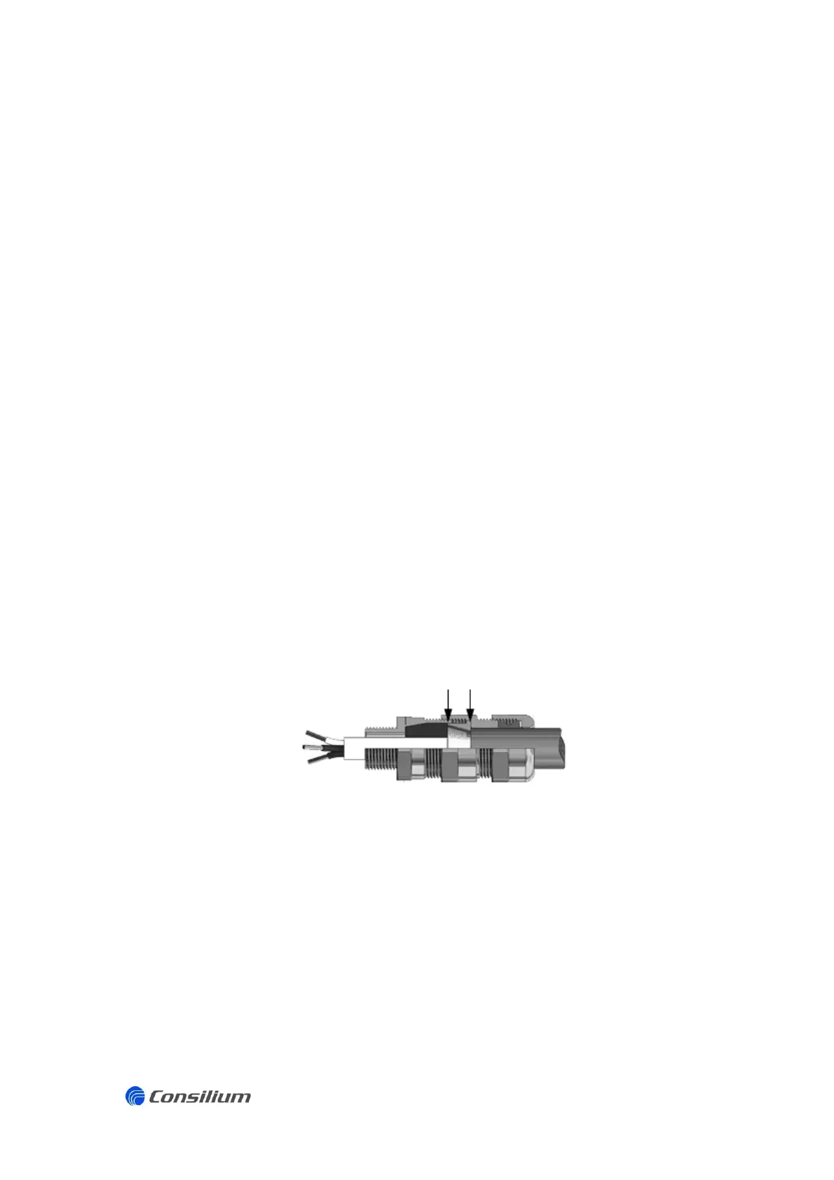
The cable screen must be mounted in the cable gland of the ST450EC sensing head.
Cut the outer cable sheath until mid-way of the cable gland.
Cut the braiding approximately 1 cm beyond the outer cable sheath.
Clamp the braid in the conical bus connection located in the centre of the gland. Ensure
the braid is in contact with the cable gland.
The inner cable sheath and the cable cores are routed to the inside of in the sensing
head.
Tighten the cable gland firmly, so that the cable is tightly secured and provides a good
strain relief.
The complete system is to be connected as a star point to ground.
Mounting shielding cable gland
Avoid running cables close to high power cables, inverters, radio transmission lines, computer
communication cables or cables carrying pulses of high current.
In a large multi-channel gas detection system with several spaced sensing heads, a screened
multicore cable and junction box can be used. Each sensing head is to be connected to the
junction box with a separate 2-core shielded cable. The shielding of the individual sensing head
cables should be connected using an EMC cable gland. The shielding of the multicore cable
should also be connected using an EMC cable gland. The junction box may not be connected to
local ground.