3. Each Component Function
12 IPC-PT/MV10 / IPC-PT/LS10 / HPC-HMV10 / HPC-HLS10 Hardware Manual
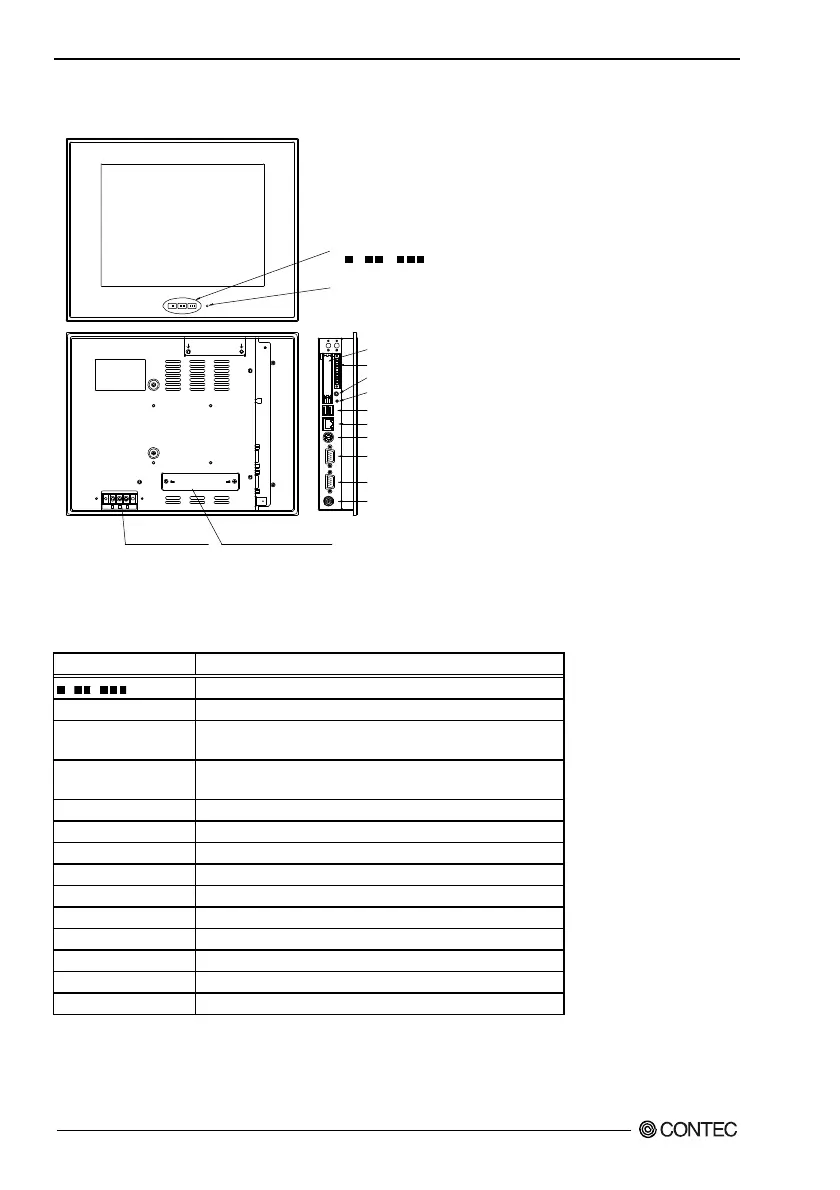
Component Locations(HPC-HMV10 series, HPC-HLS10 series)
X XX
POWER LED
Sound
PCMCIA
COM1
COM2
Keyboard
LAN
USB
RESET
I/O
VI DE O I N COM2 COM1
PCMCIA
ACT
KB
LNK
UTP USB
SPKRST
I/O
Power input
terminal strip
PCI expansion unit
connector cover
Function switch
, ,
Video
* Refer to the First Step Guide for the function switches.
Figure 3.2. Component Locations<HPC-HMV10 series, HPC-HLS10 series>
Table 3.2. Component Identification<HPC-HMV10 series, HPC-HLS10 series>
Component Function
, , Function Switch
POWER LED Power supply ON display LED
Power input terminal
strip
Power input terminal strip
PCI expansion unit
connector cover
Used to attach the PCI expansion unit and to set SW2, SW3,
SW4, and JP5
PCMCIA PCMCIA card slot
I/O Isolated I/O connector
Sound Output terminals for external speakers
RESET Hard reset push button
USB USB port connector
UTP Ethernet connector (RJ-45)
Keyboard Keyboard connector (MINI-DIN 6pin)
COM1 Serial port 1
COM2 Serial port 2
Video Video input terminator
 Loading...