3. Each Component Function
16 IPC-PT/MV10 / IPC-PT/LS10 / HPC-HMV10 / HPC-HLS10 Hardware Manual
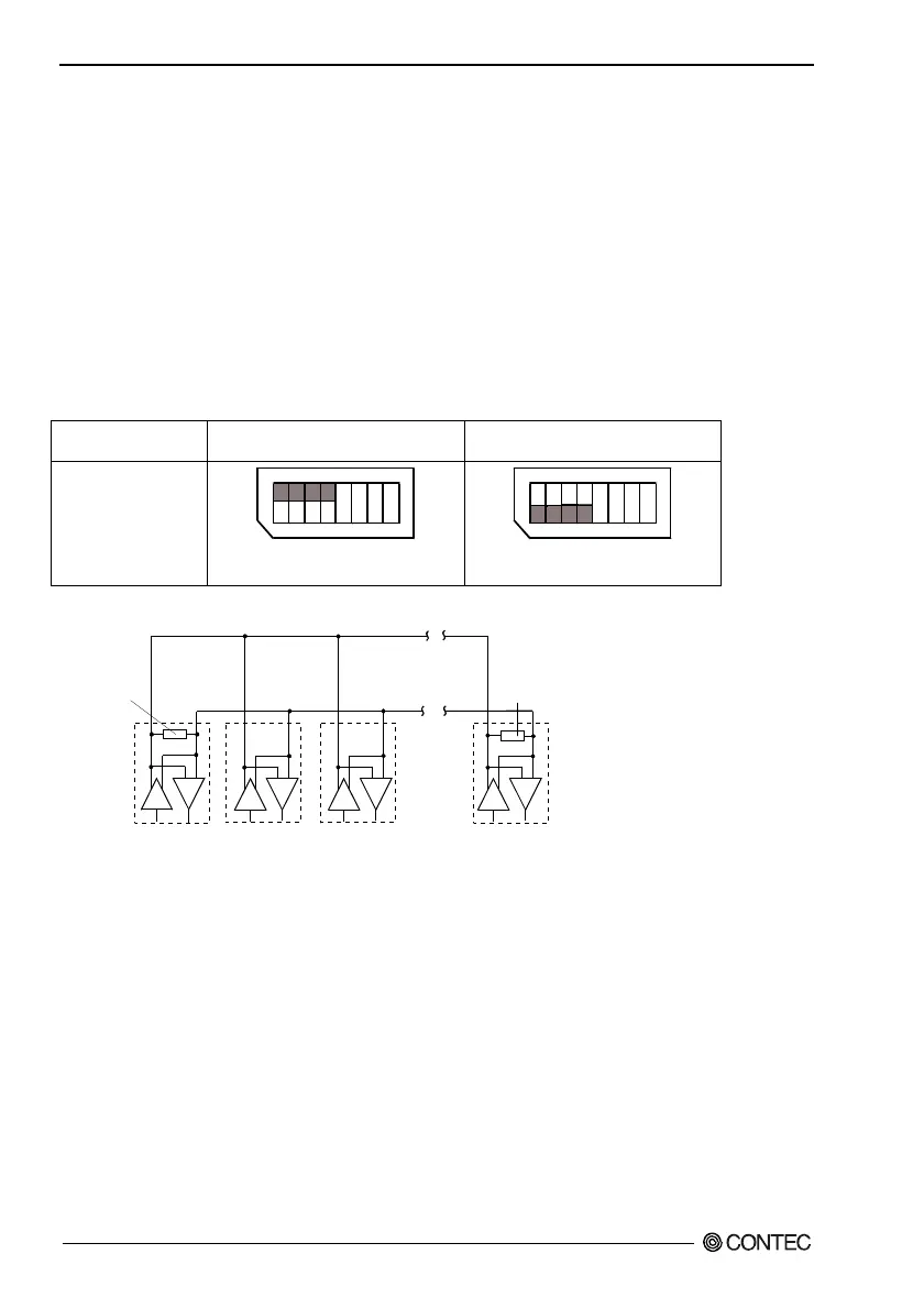
Terminating resistor setting
When inserting a terminator, use the terminator setting switch (SW4). Set the terminator depending on
the remote device to which to connect the board. The board contains a 100-ohm resistor as a
terminator. See Figure 3.5 for the presence or absence of a terminator for connection to the party line.
Individual bits correspond to different signal lines; bits 1 to 4 serve for CTS, RTS, RxD, and TxD,
respectively.
Setting method
To set the terminal to a resistor other than 100
Ω
, set the terminator setting switch to OFF and insert an
external terminator.
Table 3.7. Terminator Settings
Insert terminator
[Term ON]
Do not insert terminator
[Term OFF]
Setting method
(SW4)
1
2
3
4
5
6
7
8
ON
(A) or (D) below
(either end of signal line)
1
2
3
4
5
6
7
8
ON
(B) or (D) below
(other than end of signal line)
Terminator
Terminator
(A)
(D)
(C)
(B)
Figure 3.6. Party Line Connection
 Loading...