3. Each Component Function
IPC-PT/MV10 / IPC-PT/LS10 / HPC-HMV10 / HPC-HLS10 Hardware Manual 13
Serial Port Interface (COM1, COM2)
The PANECON-PC is equipped with two RS-232C-compliant serial port connectors (Serial Port 1:
COM1 and Serial Port : COM2).
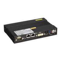
Table 3.3. COM1 Serial Port Inter Connector
Pin no.
1
2
3
4
5
6
7
8
9
Main unit connector D-SUB 9-pin (Male)
Signal
CD
RD
TD
DTR
GND
DSR
RTS
CTS
RI
Function
Carrier detection
Received data
Transmitted data
Data terminal ready
Signal ground
Data set ready
Request to send
Clear to send
Ring indicator
Direction
In
In
Out
Out
-----
In
Out
In
In
1 5
9
6
No.4-40UNC
Inch screw
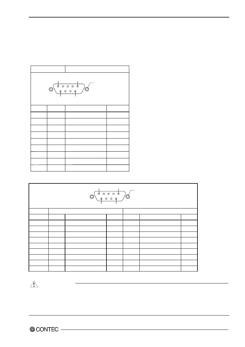
Table 3.4. COM2 Serial Port Inter Connector
1 5
9
6
No.4-40UNC
Inch screw
RS-232C (Factory setting)
RS-422A/RS485
Pin no. Signal Function Direction Signal. Function Direction
1 CD Carrier detection In GND Signal ground -
2 RD Received data In RTS+ Request send + Out
3 TD Transmitted data Out RTS- Request send - Out
4 DTR Data terminal ready Out TXD+ Transmitted data + Out
5 GND Signal ground - TXD- Transmitted data - Out
6 DSR Data set ready In CTS- Clear to send - In
7 RTS Request send Out CTS+ Clear to send + In
8 CTS Clear to send In RXD+ Received data + In
9 RI Ring indicator In RXD- Received data - In
To switch between RS-232C and RS-422/485, set the DIP-SW and JP under the PCI expansion unit connector cover.
CAUTION
For TxD, RxD, and RTS, RS-422A/485 pin assignment has even-numbered pins for positive and
odd-numbered ones for negative. For CTS, however, even-numbered and odd-numbered pins are
assigned for negative and positive, respectively, in contrast with other signals. This is not a
description error.
 Loading...