Commander SE User Guide
Issue Number 5 33
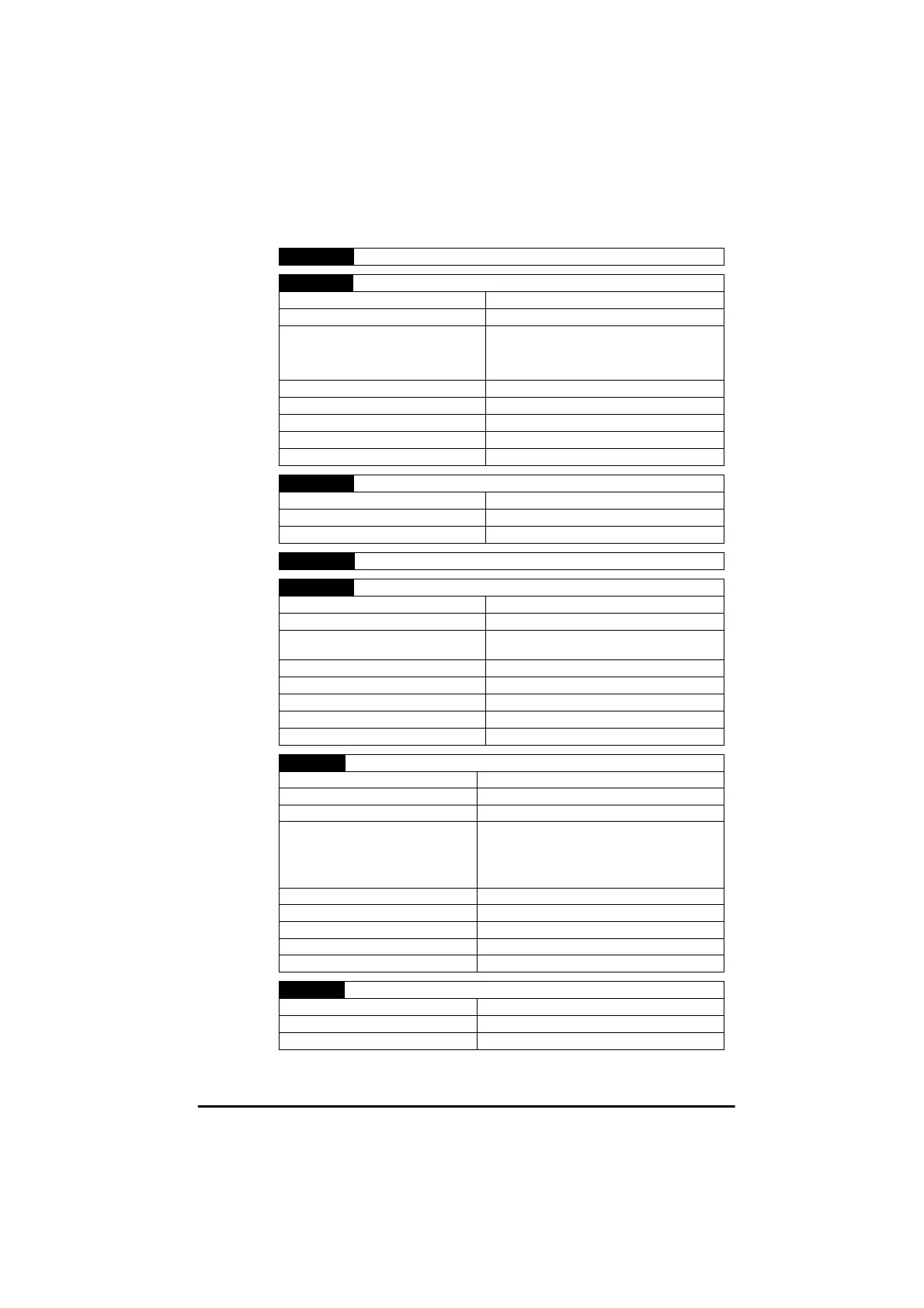
1 0V common
2 Local Speed reference input (A1)
Type of input Single-ended
Voltage range 0 to +10V
Scaling
0V represents the value in parameter 01,
Minimum speed.
+10V represents the value in parameter 02,
Maximum speed.
Absolute maximum voltage range +35V to -18V with respect to 0V common
Input impedance 100kΩ
Resolution 0.1% (10 bit)
Accuracy ± 2%
Sample time 6ms
3 +10V reference output
Voltage accuracy ± 2%
Maximum output current 5mA
Protection tolerates continuous short circuit to 0V
4 0V common
5 Remote current speed-reference input (A2)
Default 4 - .20mA (See parameter 16)
Type of input Single ended
Current range (programmable)
0-20mA, 20-0mA, 4-20mA, 20-4mA,
4-.20mA, 20-.4mA
Absolute maximum voltage range +35V to -18V with respect to 0V common
Input impedance 200Ω
Resolution 0.1% (10 bit)
Accuracy ± 2%
Sample time 6ms
6 Analog voltage output
Default Motor Speed (See parameter 36)
Absolute maximum voltage range +35V to -1V with respect to 0V common
Voltage range 0 to +10V
Scaling: Motor speed output
% full load current output
0V represent 0Hz/0 rpm output
+10V represents the value of parameter 02,
Maximum speed.
0V represent 0% Drive rated current
+10V represents 150% Drive rated current.
Maximum output current 5mA
Resolution 0.1% (10 bit)
Accuracy ± 5%
Update time 22ms
Protection tolerates continuous short circuit to 0V
7 +24V output
Voltage accuracy ± 10%
Maximum output current 100mA
Protection tolerates continuous short circuit to 0V