*
M’Ax User Guide 47
Issue Number: 4
Set 0.25 for the required maximum acceleration rate in both directions of
rotation under the following conditions:
• Starting the motor when a speed reference is already applied to the
Drive
• Rapid increases in the speed reference
Larger values produce lower acceleration.
See
0.24 Ramp enable.
Set
0.26 for the required maximum deceleration rate in both directions of
rotation under the following conditions:
• Rapid decreases in the speed reference
Larger values produce lower deceleration.
See the following:
0.24 Ramp enable
0.27 Ramp mode select
Set
0.27 as follows:
0.27 set at 0 (default)
If regenerated power during deceleration causes the maximum DC-bus
voltage (820V) to be reached, the deceleration is automatically reduced
to prevent the maximum voltage from being exceeded. This lengthens
the deceleration time.
0.27 set at 1
The motor is decelerated according to the demand (or deceleration
ramp). If regenerated power during deceleration causes the maximum
DC-bus voltage (820V) to be exceeded, the Drive will trip (trip code
OU).
0.28 indicates a number of revolutions performed by the motor shaft.
When the count passes through
65535 on clockwise rotation (run
forward), it returns to zero, then resumes counting upward.
When the count passes through zero on anti-clockwise rotation (run
reverse), it returns to
65535, then resumes counting downward.
0.28 is set at zero each time the Drive is powered-up.
0.29 initially indicates the angular position of the motor shaft relative to
its position at the time the Drive was powered-up. After the first Z marker
pulse has been received from the CT-Coder,
0.29 indicates the angular
position of the motor shaft relative to the Z marker pulse.
Set
0.30 as follows:
See also
0.31 Jog selected indicator.
The setting of
0.31 is controlled by digital input 3 (DIGITAL I/O pin 8) and
indicatesasfollows:
0.31 set at 0
No signal applied to digital input 3. The motor is controlled by the speed
reference selected by
0.30 Reference selector.
0.31 set at 1
Signal applied to digital input 3. The motor speed is controlled by 0.32
Jog reference.
Enter the required value of jog speed in
0.32.
See
0.31 Jog selected indicator.
Enter the required value of jog speed in
0.33.
See
0.30 Reference selector.
Version _
AN: 0.34 indicates the value of the speed reference set by use
of the keypad.
Version _
SL: 0.34 is not used.
See Chapter 7 Security and Accessing the Advanced Parameters.
0.25
Acceleration rate
{2.11}
ô
0 ~ 32.000
ð
0.200
RW Uni s/1000RPM
0.26
Deceleration rate
{2.21}
ô
0 ~ 32.000
ð
0.200
RW Uni s/1000RPM
0.27
Fast ramp select
{2.04}
ô
0~1
ð
0
RW Bit
0.28
Feedback-encoder revolution counter
{3.28}
ô
0 ~ 65535
RO Uni REVOLUTIONS
0.29
Feedback-encoder position
{3.29}
ô
0 ~ 65535
RO Uni 1/65536REV
0.30
Reference selector
{1.14}
ô
0~5
ð
1
RW Uni s/1000RPM
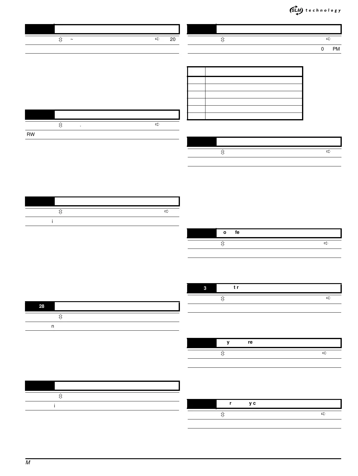
0.30 Speed reference
0(SeetheM’Ax Advanced User Guide)
1 Analog speed reference
2 Analog speed reference
3 Preset speed reference (see
0.33)
4 Keypad speed reference (see
0.34)
5 Pulse speed reference
0.31
Jog selected indicator
{1.13}
ô
0~1
ð
0
RO Bit P
0.32
Jog reference
{1.05}
ô
0~500
ð
50
RW Uni RPM
0.33
Preset reference
{1.21}
ô
+[0.08]
ð
1
RW Bi RPM
0.34
Keypad reference
{1.17}
ô
+[0.08]
ð
0.0
RO Bi RPM
0.35
User Security code
{11.30}
ô
0~255
ð
149
RW Uni S P