*
48 M’Ax User Guide
Issue Number: 4
See Appendix C Serial Communications.
See Appendix C Serial Communications.
Version _AN
Use 0.38 to specify the parameter whose value is to be displayed on the
upper line of the alphanumeric keypad when the Drive is powered-up;
this is termed the initially displayed parameter. By default, parameter
0.05 Speed feedback is the initially displayed parameter.
Normally only one of the Menu 0 parameters can be specified as the
initially displayed parameter. If
0.35 User security code is set at 0,any
parameter can be specified.
Version _SL
0.38
has no effect.
0.39 indicates 1 when both the following conditions arise:
• Motor current exceeds 110% of the rated motor current
• The value in the overload accumulator in the SLM exceeds 75%
Version _
AN: The lower line of the alphanumeric display indicates the
alarm
OuL.
If the motor current is not reduced, the Drive will trip due to excessive
motor current (trip code:
I2t.AC).
0.40 indicates the value of a motor thermal-overload accumulator in the
Drive that monitors the power delivered to the motor. If the value reaches
100%, the lower line of the alphanumeric display (version _
AN) indicates
the alarm
OuL (the Drive continues controlling the motor). If the value
exceeds 100%, the Drive will trip; the display then indicates
I2t.AC.
0.41 indicates the value of an I
2
t accumulator that monitors the output
power of the Drive. If the value exceeds 100%, the Drive will trip; the
lower line of the alphanumeric display (version _
AN) then indicates
O.ht1.
0.42 indicates the value of the of an I
2
t accumulator that monitors the
power dissipated in the internal braking resistor. If the value exceeds
100% (representing 150W), the Drive trips; the lower line of the
alphanumeric display (version _
AN) indicates It.br.
0.42 indicates the value of the DC-bus voltage.
0.44 indicates the trip code of the last trip.
0.45 indicates 1 when
)
technology data links are operating correctly.
0.46 can be assigned to any advanced parameter and given a scaling
factor. A typical use would be indicating the rate of flow in a way that is
meaningful to the production process (e.g. cans per hour).
The default function is as follows:
0.01 x [0.05] Speed feedback
See Optional setting-up in Chapter 6 Setting Up the Drive for Basic
Applications.
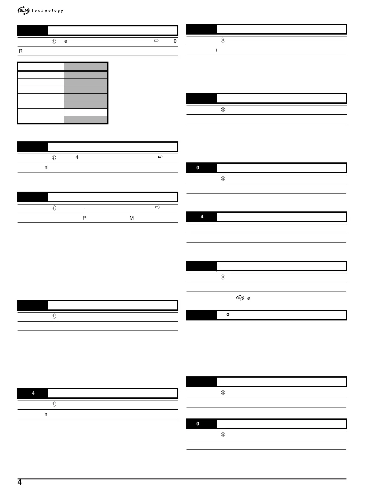
0.36
Serial comms. baude rate
{11.25}
ô
(see below)
ð
9600
RW Txt S P BAUD
Baud rate
300
600
1200
2400
4800
9600 Default
19200
0.37
Serial comms. address
{11.23}
ô
0.0 ~ 24.7
ð
1.1
RW Uni P GROUP.UNIT
0.38
Initial parameter displayed selector
{11.22}
ô
00.00 ~ 21.51
ð
0.05
RW Uni P MENU.PARAMETER
0.39
Motor [I
2
t] overload alarm indicator
{10.17}
ô
0~1
RO Bit P
0.40
Motor I
2
t accumulator
{10.58}
ô
0.0 ~ 100.0
RO Uni %
0.41
Drive overload accumulator
{10.56}
ô
0.0 ~ 100.0
RO Uni P %
0.42
Internal braking-resistor overload accumulator
{10.39}
ô
0 ~ 100.0
RO Uni P %
0.43
DC-bus voltage
{5.05}
ô
0 ~ 1000
RO Uni P V
0.44
Last trip
{10.20}
RO Txt S P
0.45
SLM communications integrity
{11.56}
ô
0~100
RO Uni
0.46
Programmable parameter
0.47
SLM software version
{11.39}
ô
00.99 ~ 99.99
RO Uni P
0.48
Drive software version
{11.29}
ô
1.00 ~ 99.99
RO Uni P