*
80 M’Ax User Guide
Issue Number: 4
SIM ENC
Connecting cable for simulated-encoder signals
When the encoder feedback is to operate at greater than 4096 pulses
per revolution, a suitable connecting cable must be used. Each line pair
must be terminated at the system controller or PLC by a resistor of an
appropriate value.
Analog outputs
The analog outputs (pins 9 and 11) are intended for
indication purposes, not for use in process control.
The signal level on Analog output 2 may become
inaccurate at the following occasions:
During the process of saving parameter values
At power-up and power-down
Any cable connecting to the SIM ENC connector should
have its cable shield connected to Pin 15. Failure to do
so could result in the Drive being damaged.
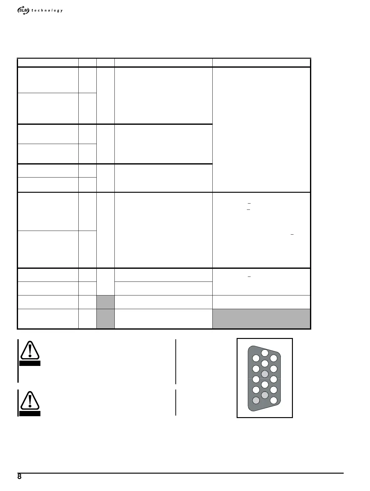
Figure A.3 Female D-type connector pin-locations (as seen from
the top of the Drive)
Name Pin I/O Function Specification
Simulated encoder
quadrature A output
Frequency output
1
O
Dual-function output, used for:
Simulated encoder A output derived from
the CT-Coder on the motor (default
function)
Frequency output (direction output on pins
6, 7)
Use for feedback to a system controller, plc
or motion controller, plc or motion
controller, or for digital another Drive
EIA 485 differential outputs
Connecting cable: Three shielded twisted-
pairs inside an overall shield
Simulated encoder
quadrature A \ output
Frequency output \
2
Simulated encoder
quadrature B output
Direction output
6
Dual-function output, used for:
Simulated encoder B output derived from
the CT-Coder on the motor (default
function)
Specifying direction when pins 1 and 2 are
used for frequency output
Simulated encoder
quadrature B \ output
Direction output \
7
Simulated encoder Z
output
13
Marker pulse output available only when
quadrature A B outputs are used
Simulated encoder Z \
output
14
Standard-precision
analog input
3
I
Speed-reference input available only in
version _
SL
Differential analog input
Voltage range: +
10V
Voltage offset: <
20mV (equivalent to 10-bit
resolution)
Resolution: 12-bit (in speed mode)
Sample time: 250
µs~32ms
Maximum common-mode voltage: +
25V
relative to 0V
Linearity: 800ppm (full-scale)
Full-scale accuracy before the analog input
is calibrated: 8%
Input impedance: 16k
Ω
Standard-precision
analog input \
4
Analog output 2
9
O
TORQUE output signal (default function)
Voltage range: +
10V
Maximum output current: 1mA
Update time: 1ms
Analog output 1
11 SPEED output signal (default function)
0V 12
For use only with all the I/O on this
connector
0V must not be interchanged with 0V
COMMON
Cable shields 15
When the cable is required to be shielded
(see above), connect all the cable shields
to this pin
CAUTION
CAUTION
5
10
8
15
9
11
12
13
14
7
6
2
1
4
3