*
M’Ax User Guide 81
Issue Number: 4
MC/EIA485
EIA connections
Terminate EIA485 connections at the Drive by connecting across the
related input terminals a resistor whose value equals the characteristic
impedance of the cable that is being used. When more than one Drive is
connected to an EIA485 link, a terminating resistor is required only at the
last Drive on the link.
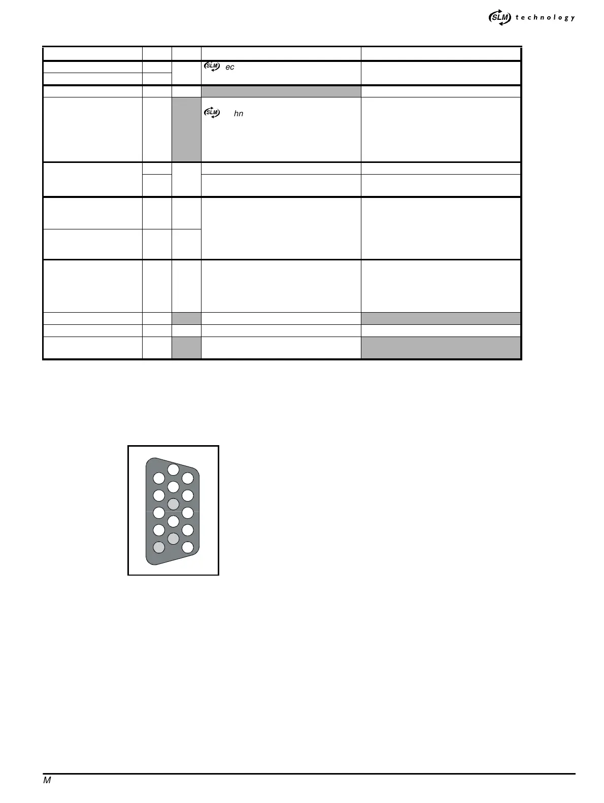
Figure A.4 Female D-type connector pin-locations (as seen from
the top of the Drive)
Name Pin I/O Function Specification
com 1
I/O
)
technology port for bi-directional
communications with a motion controller
2-wire EIA485
Connecting cable: Shielded twisted pair
com\ 2
Hardware enable 3 I
(See Digital inputs on page 77.)
0V COMMON
12
15
For use with:
)
technology com and com\
Hardware-enable
SLM-and-user back-up supply
EIA485 ports
24V user supply
0V COMMON must not be interchanged
with 0V
SLM-and-user back-up
supply
5
I
+24V input (See 24V user supply on page 77.)
40V
0V COMMON must not be interchanged
with 0V
EIA 485RX
EIA 485RX \
6
7
O
Bi-directional communications port for
control by system controller or PLC
4wireEIA485
Connecting cable: Two shielded twisted
pairs inside an overall shield
Unit load: 3.5
Line termination: (see below)
Line bias resistors: 12
Ω
EIA 485 TX
EIA 485 TX \
13
14
I
Status-relay contact
8
10
O
DRIVE HEALTHY
Relay contact opens if the Drive trips
Voltage rating: 50VAC/DC category 2
Current rating: 1A resistive
Update period: 500
µs
Default source parameter:
10.01 Drive
healthy indicator
(No connection) 9
Do not use
24V user supply 11 O 24V supply for external control circuits (See 224V user supply on page 77.)
Cable shields Shell
Connect all the cable shields to the
connector shell
5
10
8
15
9
11
12
13
14
7
6
2
1
4
3