18 Issue Number: 3
5.3 Profibus-DP Data Formats
The Unidrive Profibus-DP interface will auto-detect the data format
required during network initialisation. Consistency can be selected
when the master controller is configured.
Non-cyclic
mode
Cyclic
words
Consistency Comments
1 3 Full
1 3 None
These modes are supported by
Mentor II and Commander SE
1 3 Full 8 bytes with full consistency,
available for backwards
compatibility with older modules
5.4 Mapping Parameters on Unidrive
The mapping for the cyclic data channels on the Unidrive Profibus-DP
interface can be set from the Unidrive keypad using #20.PP
parameters.
The mapping method is similar to the method used for mapping
analogue inputs and outputs. The value entered in the mapping
parameter takes the form MMPP, where MM = menu number of the
target parameter and PP = parameter number of the target parameter.
NOTE
#20.01 to #20.20, and #20.50 are all reserved for Profibus-DP set-up
and configuration, and should not be used in DPL programs.
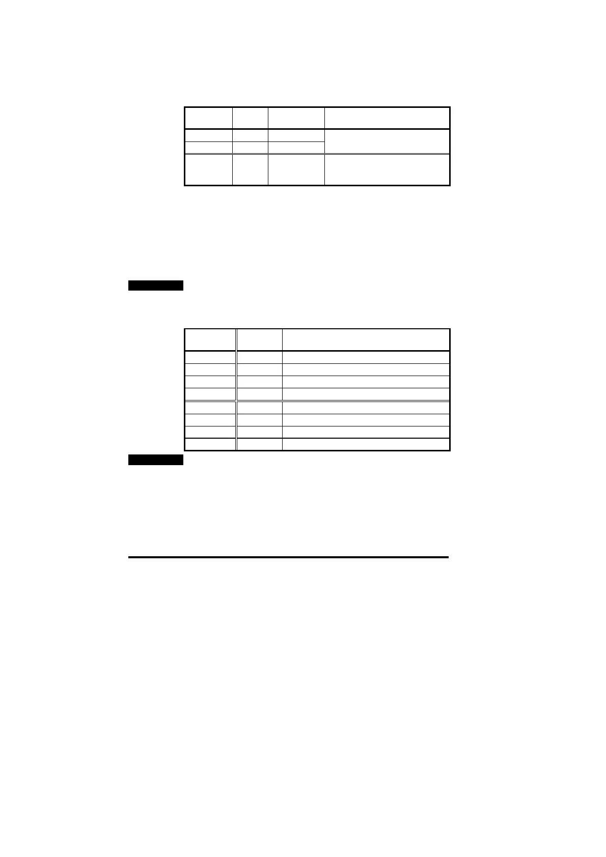
The default mapping values are shown in the table below.
Cyclic
Channel
Mapping
Parameter
Default Mapping Status
IN Word 0 ---- Reserved for the non-cyclic data
IN Word 1 #20.07 #90.11, fieldbus status word
IN Word 2 #20.03 #2.01, post-ramp speed reference
IN Word 3 #20.04 #4.02, torque-producing current
OUT Word 0 ---- Reserved for the non-cyclic data
OUT Word 1 #20.06 #90.11, fieldbus control word
OUT Word 2 #20.01 #1.21, digital speed reference 1
OUT Word 3 #20.02 #4.08, torque reference
NOTE
If a mapping parameter is set to an invalid value, e.g. destination
parameter is read only, or parameter does not exist, the Unidrive will
reset the mapping parameter (#20.PP) to its default value.
If a cyclic channel is not required, setting the mapping value to -1 will
disable it. The data word will still be transmitted over the network, but
the data value will not be written to any Unidrive parameter.