Issue Number: 3 7
3 Electrical Installation
3.1 Profibus-DP Connectors
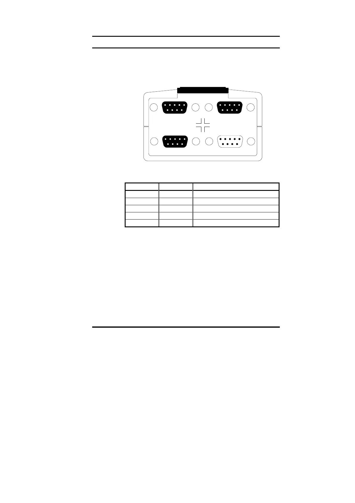
The Unidrive Profibus-DP interface has two 9-way D-type sockets (A
and B) to connect to the Profibus-DP network. Connectors C and D are
the RS232 programming port (C) and RS485 general-purpose
communications port (D) of the UD70.
AB
DC
The Profibus-DP connectors are parallel connectors, so either
connector can be used. The pin-out connections are identical, and are
given in the table below.
Terminal Function Description
8 A Negative data Line
3 B Positive data Line
5 0V ISO 0V Isolated
6 V
DC
+5V line for termination resistors
Shell Screen Cable braided screen connection
3.2 Profibus-DP Data Connections
Specifically designed connectors are available for use on Profibus-DP
networks that accept 2 Profibus-DP cables into colour-coded screw
terminals, and plug directly into a 9-way Profibus-DP D-type connector.
A screen clamp is also included to ensure good screen continuity and
provide the best possible immunity to noise. Control Techniques
recommends that a suitable connector should be used to connect the
Unidrive Profibus-DP interface to a Profibus-DP network.
Details of manufacturers of connectors approved for use with Profibus-
DP can be found on the Profibus web site at “www.profibus.com“.