Issue Number: 3 31
TELEGRAM 4
The fourth telegram from the master has the stamp number set to 4.
The data bits contain the data low byte for the parameter that is being
written to.
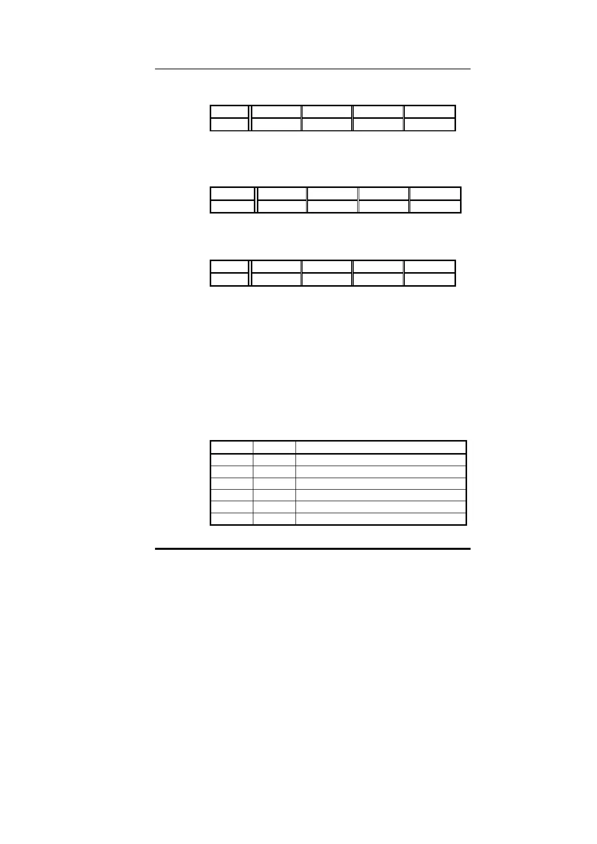
Bit b15-b12 b11-b8 b7-b4 b3-b0
Value 0XXX 0100 1011 0000
Data word = 0x04B0 Stamp number = 4 Low data byte = 0xB0
When the fourth telegram has been received and processed in the
slave node, it will write the data (#1.21 = 1200) as transmitted, ignoring
the decimal point. If the operation is successful, the ERR bit is reset to
0 and the telegram is reflected in the non-cyclic IN word.
Bit b15-b12 b11-b8 b7-b4 b3-b0
Value 00XX 0100 1011 0000
Data word = 0x04B0 Stamp number = 4 Low data byte = 0xB0
If there was a problem with writing the data to the defined parameter,
e.g. parameter is read only, does not exist, or data is out of range, the
ERR bit is set to 1.
Bit b15-b12 b11-b8 b7-b4 b3-b0
Value 01XX 0100 XXXX XXXX
Data word = 0x4400 Stamp number = 4
6.2 Profibus-DP Set-up using Non-Cyclic Data
The Unidrive Profibus-DP interface can also be configured via the non-
cyclic data channel. Menu 20 in the Unidrive contains the parameter
values currently being used, and these can be modified as required.
Cyclic data mapping parameters can be edited via the non-cyclic data,
but changes made to the data mapping will not take effect until the
UD70 has been reset.
Setting #17.19 to 1 will store the mapping changes in the Profibus-DP
interface, and reset the Profibus-DP interface. The Profibus-DP master
controller may detect an brief error while the Unidrive Profibus-DP
interface resets and re-configures itself.
The parameters listed below are the parameters that can be written to
configure the Profibus-DP interface.
Param Default Description
#20.07 #90.11 Not used
#20.03 #2.01 IN Channel 2 Mapping
#20.04 #4.02 IN Channel 3 Mapping
#20.06 #90.11 OUT Channel 2 Mapping
#20.01 #1.21 OUT Channel 3 Mapping
#20.02 #4.08 Load Option Defaults