Issue Number: 3 21
5.7.1 Control Word Mapping Conflicts
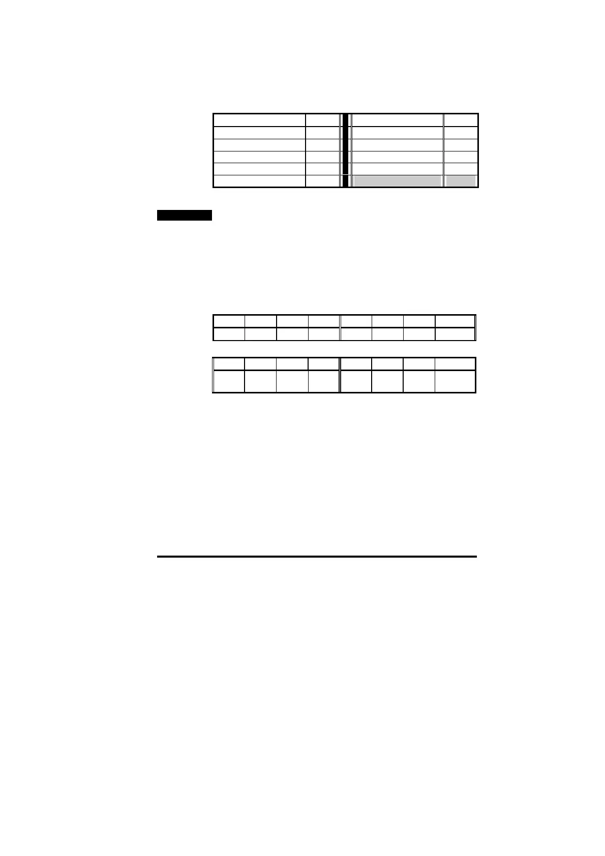
The control word provides a method of writing to multiple bit parameters
using one data word. If one of the cyclic data channels is writing to the
control word, the following bit parameters for each Unidrive must not be
controlled by any digital inputs.
Function Param
Function Param
Enable #6.15 Preset ref select bit 1 #1.46
Run Forwards #6.30 Application bit #18.31
Jog #6.31 Application bit #18.32
Run Reverse #6.32 Application bit #18.33
Preset ref select bit 0 #1.45
5.8 Fieldbus Control Word for Unidrive
NOTE
This section assumes that the Unidrive is configured to use the
default Wire Proof PLC sequencing mode (#6.04 = 4). If PLC mode is
selected (#6.04 = 3), the control word mapping is slightly different.
Refer to section 9.2 for details.
The Control Word is an efficient way of remotely controlling the motion
of a Unidrive. Each bit in the control word has a particular function, and
provides a method of controlling the function of the Unidrive (RUN,
JOG, etc.) with a single data word. The control word is addressed in
the UD70 by writing to #90.11.
b15 b14 b13 B12 b11 b10 b9 b8
M6 M5 #18.33 M3 M2 M1 M0 #18.32
b7 b6 b5 b4 b3 b2 b1 b0
#18.31 #1.46 #1.45 TRIP RUN
REV
JOG RUN
FWD
ENABLE
The bits shown as “Mx” are individual mask bits that allow the
corresponding "bx” to be masked, i.e. the MASK bits determine whether
or not the data bit is written through to the corresponding parameter.