ALSPA PROFIBUS Field Bus Coupler 3. Installation
(09/06) Technical Manual Page 3-15
Connectors conforming to the PROFIBUS standard are
recommended, e.g. DIN 41652.
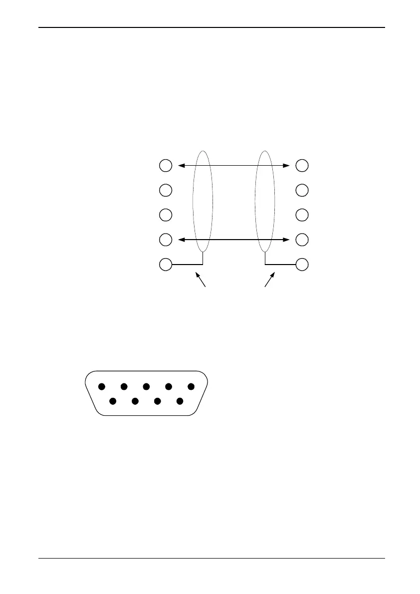
Note that the making of a ‘T’ in the PROFIBUS network is not
allowed, the cable must always be daisy-chained, as shown in
Figure 3-10 below.
Protective earth (ground)
3
6
5
8
1
3
6
5
8
1
Station 1 Station 2
DATA +
+5 V Isolated
GND Isolated
DATA -
Figure 3-10 Interconnecting two PROFIBUS stations
3.7.3 9 Way DIN Connections
Figure 3-11 Pin-out of the PROFIBUS 9 pin D-type connector
The PROFIBUS connections are as follows:
Pin 1 = Protective earth (PE) or screen.
Pin 3 = DATA+
Pin 5 = GND (isolated)
Pin 6 = +5V (isolated)
View looking into the
mating face of the
connector.
12345
6789