ALSPA PROFIBUS Field Bus Coupler Appendix A.Configuration Example
(09/06) Technical Manual Page A7
P75.30 11.30 Transmitted status word 1 source
The Fieldbus parameters now contain a basic configuration.
A.9 Data for Master Device Configuration
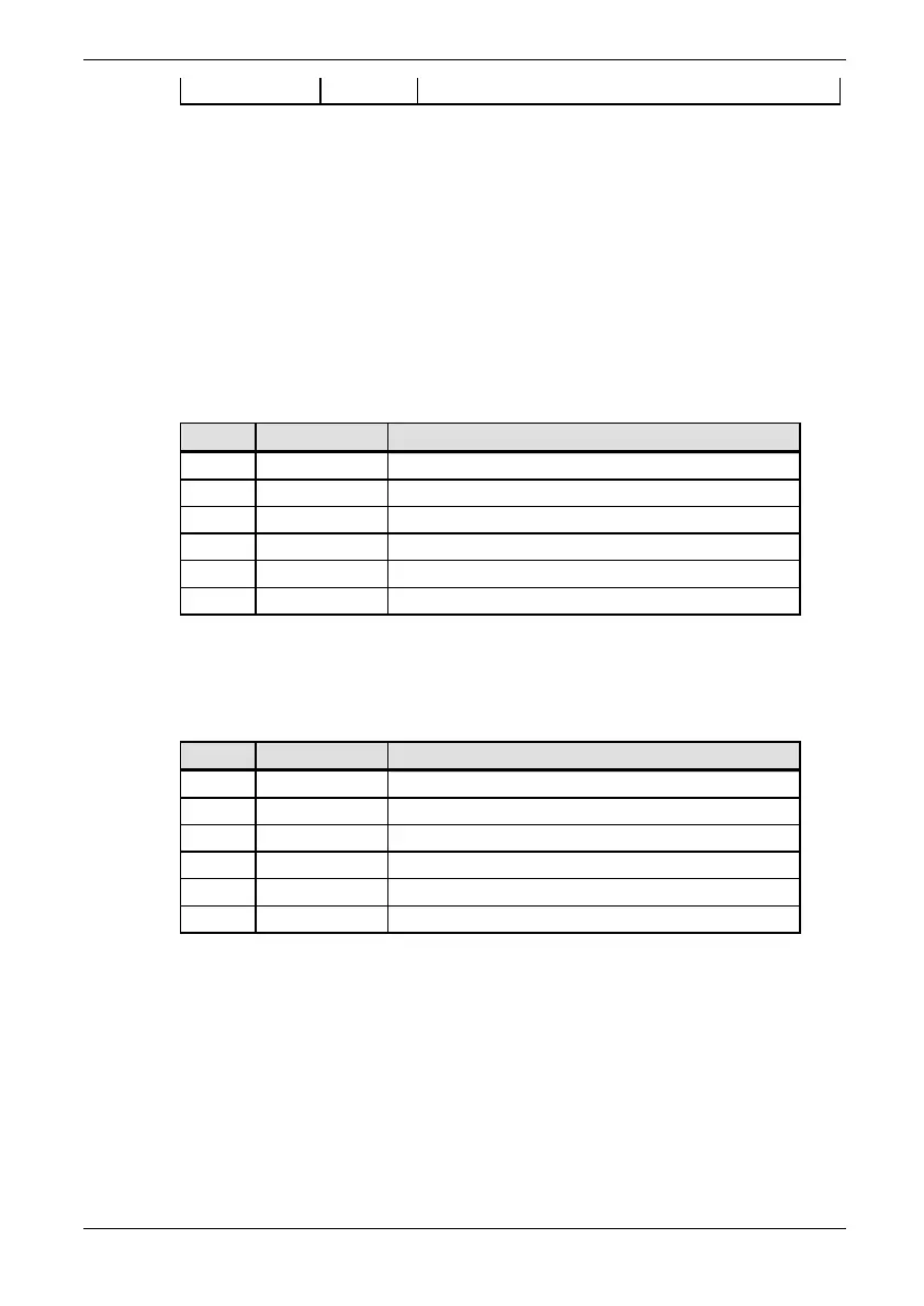
The PROFIBUS-DP master device producing the data for this drive
should now be configured. The data required to get the drive
running is shown in Table A-10.
Table A-10 PROFIBUS-DP Master’s data allocation
Word
Value Meaning
0 XXXXH Contains the run/stop bits
1 5000 Set the speed reference to 50%
2 150 Set the drive minimum speed to 150 rpm
3 0 Not used
4 0 Not used
5 0 Not used
The data produced by the drive is listed in Table A-11 below:
Table A-11 PROFIBUS-DP Master’s received data
Word Units Meaning
0 Binary flags Contains the drive status bits
1 0.01% Speed feedback.
2 0.01% Torque demand.
3 0 Not used
4 0 Not used
5 0 Not used
A.10 Using PROFIBUS Data Spy
Having parameterised a basic configuration, the user may wish to
know what data is actually being transferred over the PROFIBUS
network. This can be done using the PROFIBUS spy module. The
PROFIBUS spy module uses P75.36 to P75.41 to display each of
the 6 PZD words associated with the received PPO.