9751 Installation Guide 3. Installation
11976798 Page 17
2. Hold the backplate in place against the wall and mark the position of one
fixing hole.
3. Drill and plug the hole, and screw the backplate to the wall. Do not
tighten the screw completely home.
4. Make sure the backplate is level and mark, drill and plug another fixing
hole. Tighten the fixing screws.
6. Mount the front of the keypad (containing the keypad pcb) onto the
backplate and make sure that the tamper switch operates.
Wiring the Control Unit
Cable Entries
The control unit case back provides several cable entries. It is designed to
stand away from the wall to leave space for the cables.
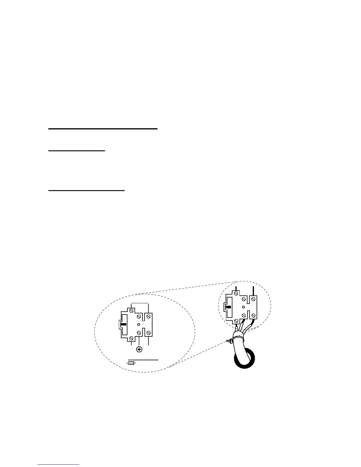
Mains Connection
Connect the control unit to a suitable supply using a double pole disconnect
device in accordance with EN60950-1:2001 Clause 3.4.3. Connect the supply
to the control unit using the 3-way terminal block located on the case back.
Secure the cable to the case anchor point using the cable tie provided.
Notes:
1. The control unit has a T-250mA internal mains fuse.
2. All electrical connections should be carried out by a qualified
electrician.
To Control Panel
Transformer
L
N
T 250mA 250V
230V ~50Hz 200mA
Figure 6. Mains Connection
Connect the 21VAC lead from the mains transformer to the main PCB. See
Figure 3 for the location of the 21VAC connector.