9751 Installation Guide 3. Installation
11976798 Page 23
Some PIR detectors are fitted with an anti-masking facility to detect cases
where the detector has been obscured. Depending on the type of detector,
the masking status is conveyed by one of two methods:
• Method 1: Using two pairs of contacts at the sensor. One pair reports the
alarm/tamper status and the other reports the anti-masking status. This
method requires two adjacent zones to be used at the 9751 control unit
(one for each pair of contact at the sensor), with the highest zone number
for anti-masking. For example, you could use zones 3 and 4, and in this
case, zone 3 must connect to the alarm/tamper contacts, and 4 to the anti-
masking contacts. The anti-masking zone (zone 4 in this example) must be
programmed as type "Anti-Mask". The alarm/tamper zone could, for
example, be programmed as type "Normal Alarm".
The anti-masking contacts from the sensor can connect to the 9751 using
the CCL, FSL or EOL connection method. In the case of FSL, there would
be no in-line tamper contacts (just the 2K2 end-of-line resistor and the 4K7
resistor across the anti-masking contacts). In the case of CCL, the zone's
tamper terminals at the 9751 must be shorted.
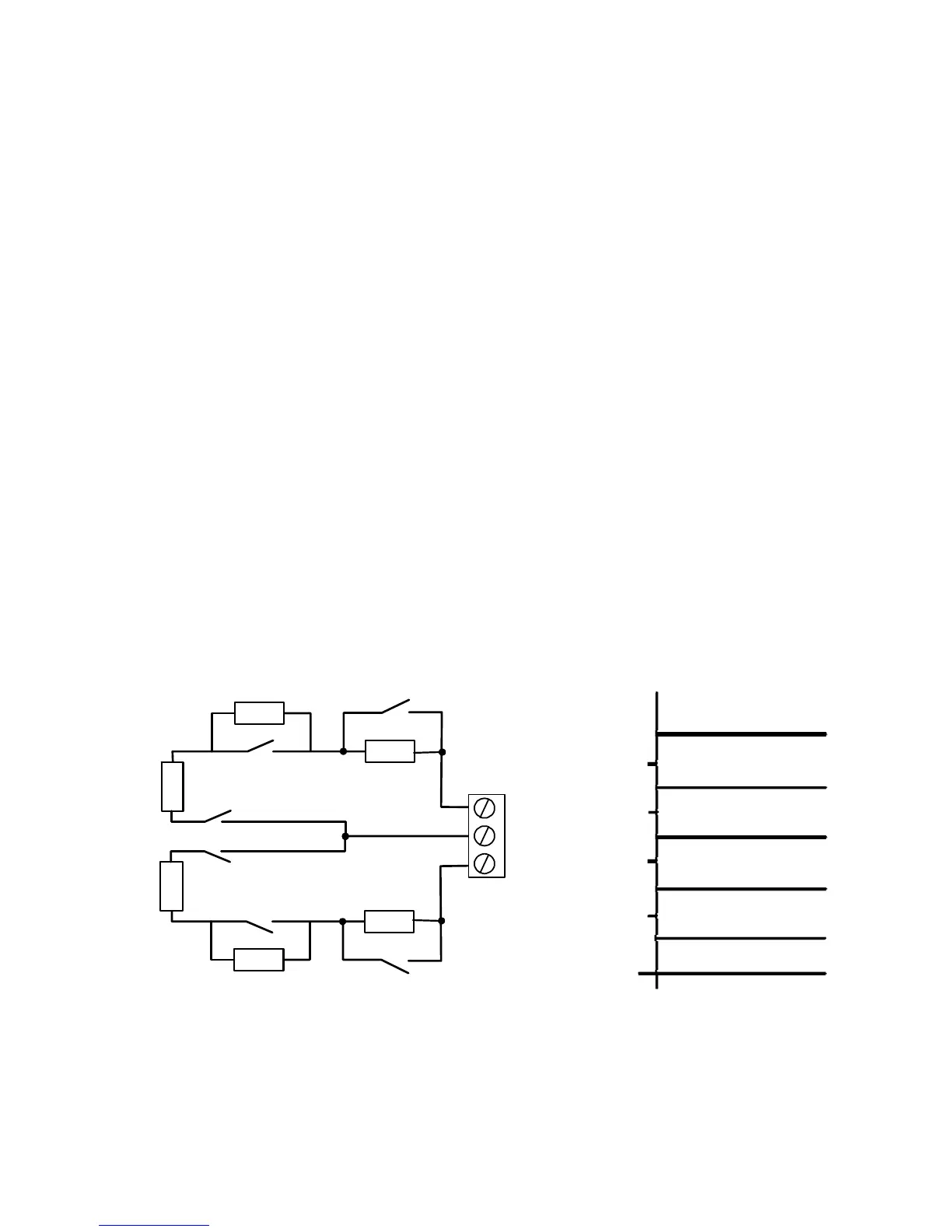
• Method 2: Applying a specified resistance value to a zone. The zone must
be wired as shown in Figure 14.
Note: Depending on the sensor, a 4K4 resistance means either
"masked" or "fault". Use command 88 to specify which reporting method
to use. All sensors with anti-masking contacts must use a 4K4 resistance
for the same meaning (masked or fault).
Short Circuit Tamper Alarm
Open Circuit Tamper Alarm
Zone
Resistance
Healthy
Sensor
failure/Fault/Masked
Masked
Alarm
9.1k
2.2k
4.4k
6.9k
2K2
2K2
2K2
2K2
4K7
4K7
Tamper
Zone 1
Zone 2
Tamper
Alarm
Alarm
Anti-mask
Anti-mask
Figure 14. Wiring Zones that use Anti-Masking