3. Installation 9751 Installation Guide
Page 22 11976798
tamper device opens, the loop resistance becomes infinite (open circuit) and
so the control unit detects a tamper signal.
To connect a detector to an FSL loop, you must wire suitable high-tolerance
resistors to the detector. Always check resistor colour coding and tolerance
before wiring resistors into circuit (see Figure 13).
The wiring resistance of the cable to the detector (including joints) should not
exceed 100 ohms. The recommended maximum cable length within a zone is
200–300m.
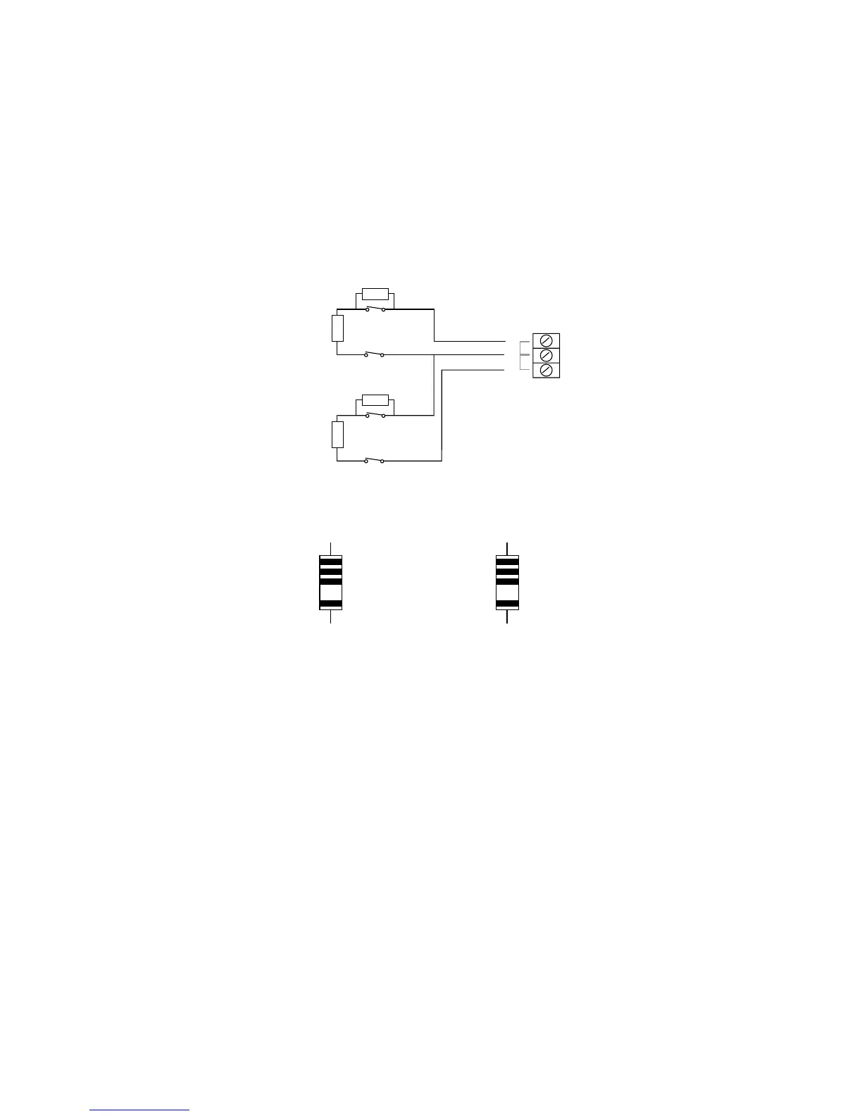
Zone 1
Zone 2
1
2
2K2 EOL
4K7
Alarm contacts
Tamper contacts
2K2 EOL
4K7
Alarm contacts
Tamper contacts
Figure 12. FSL Connections
Yellow
Violet
Red
Gold
4k7
Red
Red
Red
Gold
2k2
Figure 13. Colour Code for FSL Resistors
Anti-Masking Zone Connections
Note: Connecting an anti masking detector to the 9752 does NOT make the
9752 a Grade 3 control unit.