9751 Installation Guide 3. Installation
11976798 Page 33
Fitting a Plug-by Communicator
The control unit can be fitted with a communicator or speech dialler (for
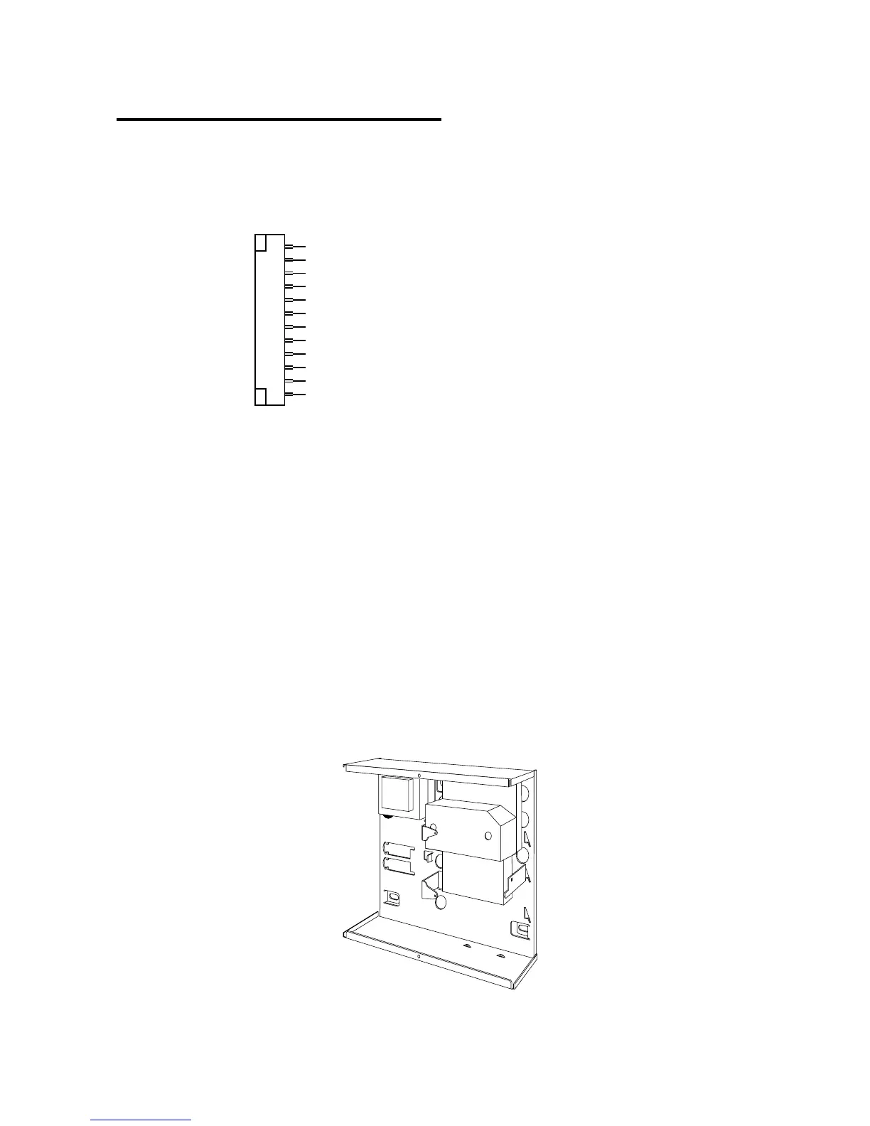
example, the Scantronic 8400, 8440, 660 or RedCare STU). Figure 24 shows
the connections for the communications wiring harness.
Comms O/P1 (Brown) -ve applied (+ve removed) in alarm
Comms O/P2 (Orange) -ve applied (+ve removed) in alarm
Comms O/P3 (Yellow) -ve applied (+ve removed) in alarm
Comms O/P4 (Green) -ve applied (+ve removed) in alarm
Comms O/P5 (Blue) -ve applied (+ve removed) in alarm
Comms O/P6 (Purple) -ve applied (+ve removed) in alarm
Comms O/P7 (White) -ve applied (+ve removed) in alarm
Comms O/P8 (Grey) -ve applied (+ve removed) in alarm
Line Fail input (White/Brown) +12V applied to indicate telephone line fail
Tell Back input (White/Orange) +12V applied to change from engineer to customer reset
0V (Black)
12V (Red)
Com Connector Cable, Part No. 485210
Figure 24. Plug-By Communicator Wiring
Note: Comms O/P4 will be active when the system is unset. This is normal, as
a system being unset is equivalent to an alarm signal.
To fit a communicator, follow the instructions below.
Caution: Follow the instructions in the order shown, or you may damage
the control unit and/or communicator.
1. Disconnect mains and battery power from the control unit and remove
the case lid, if the system has already been installed.
2. Detach the main PCB from the support pillars in the control unit case,
and lift the PCB carefully to the left. Fit the communicator between the
PCB support pillars, making sure that the main PCB can fit back into
position (see Figure 25).
Figure 25. Fitting a Plug-by Communicator