9751 Installation Guide 3. Installation
11976798 Page 19
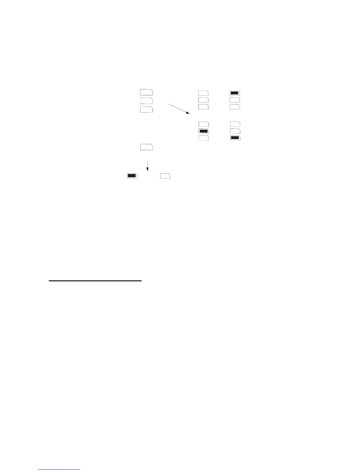
Keypad Addressing
The control unit is supplied with one keypad. If you have fitted more keypads,
each one must be given a separate "address". Links LK2 to LK4 set the
keypad address, as shown in Figure 9.
2
3
4
ON
BACKLIGHT
2
3
4
2
3
4
2
3
4
2
3
4
ON
BACKLIGHT
ON
BACKLIGHT
Keypad 1
Address
Backlight ON Backlight OFF
Keypad 2
Keypad 3 Keypad 4
Figure 9. Keypad Addressing
Backlight
When supplied from the factory, the control unit is configured with the
backlight On. To turn the backlight Off, remove the jumper from the "ON
BACKLIGHT" link, shown in Figure 9.
Connecting Sounders
Figure 10 and the following tables show the wiring required to connect the
external sounder (bell box) and optional internal sounders.
Note: If a 2k2 resistor is fitted at the tamper return (TR) terminal at the bell
box, use Command 59 to select this EOL mode of termination.
Note: The ST terminal on the control panel PCB is the Siren Test output for
France only. Do not connect it to the strobe input on the external sounder.
See Command 81 in the Programming Guide and the output wiring examples
on page 27.