9751 Installation Guide 3. Installation
11976798 Page 21
Connecting Detector Circuits to the Main PCB
The connectors for the detector circuits, or zones, are on the left-hand edge of
the main PCB in the control unit. The table below summarises the number
and type of zones that can connect to the main PCB of the control unit. Use
Command 21 to specify which of these wiring types you are using. You
cannot specify different wiring types for different zones.
If you require more zones, fit one or more expanders as explained on page
22). There can be up to 16 zones on expanders.
Control Unit Wiring Type
Zones
8 four-wire CCL with common tamper
8 two-wire FSL
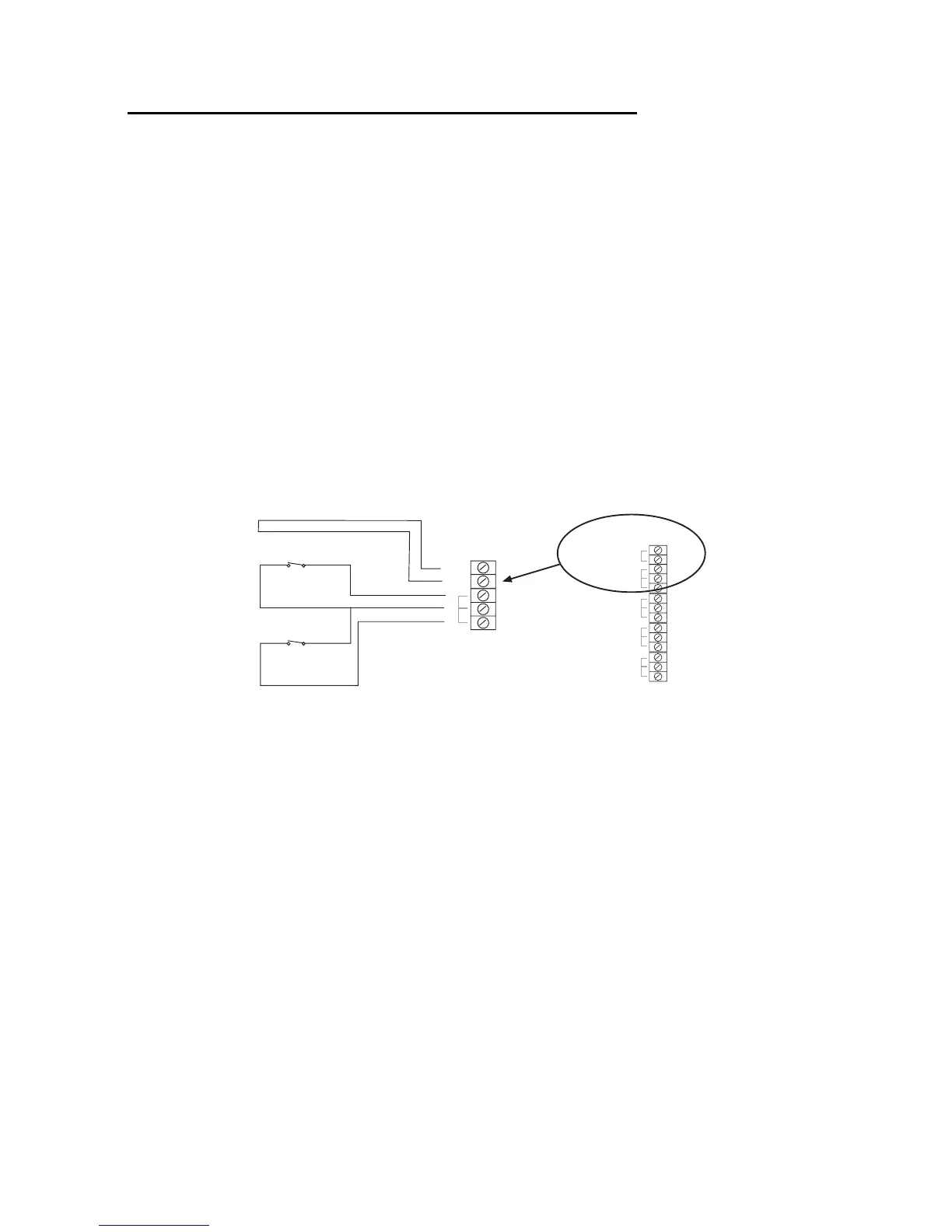
CCL Connections
Figure 11 shows how to connect four-wire CCL zones.
1
2
Zone 1
Zone 2
Global Anti-tamper
Zone 3
Zone 4
Zone 5
Zone 6
Zone 7
Zone 8
Tamper loop
Zone 1
Zone 2
Alarm contacts
Alarm contacts
Figure 11. CCL Connections (common tamper)
NOTE: If you use CCL wiring then you must program zone 1 as Normal Alarm
(see 9x5x Programming Manual) and fit a wire link to Zone 1 terminals in
order to enable the global tamper.
FSL Connections
Each FSL zone is a "Fully Supervised Loop" using a two-wire closed loop. As
shown in Figure 12, the loop uses resistors of different values to differentiate
between "Circuit" and "Tamper" signals: a 2K2 resistor fitted in series at the
end of the wired loop (EOL) and a 4K7 resistor fitted across the alarm contact.
With the loop in a normal state and the alarm contacts closed (shorting out the
4K7 resistor), the total resistance of the loop is 2K2. When the alarm contacts
open (removing the short from the 4K7 resistor), the resistance of the loop
increases to 6K9 and so the control unit detects an alarm condition. If a