3. Installation 9751 Installation Guide
Page 34 11976798
3. Make any necessary connections from the communicator to the
communication wiring harness. The default is a positive voltage when the
output is inactive but this can be inverted if required using Command
159.
Refer to the next section if you are using a dual-path communicator.
4. Plug the Communication Wiring Harness onto the communications
connector on the main PCB.
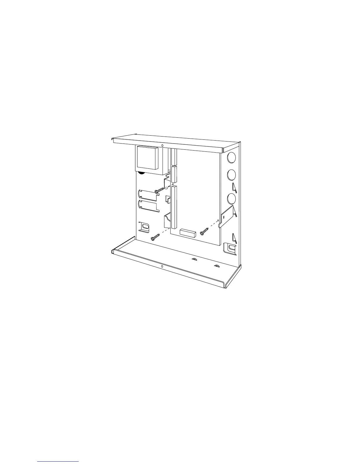
5. Re-fit the PCB to the support pillars. Secure the PCB to the support
pillars with the screws provided (Figure 26). Make sure that the bottom
left corner of the PCB is seated on its support pillar.
Figure 26. Fitting Control Unit PCB
If the system has already been installed:
6. Re-connect the battery.
7. Fit the case lid.
8. Apply mains power.
9. Test communicator operation.