9751 Installation Guide 3. Installation
11976798 Page 27
OP3
+ve 12V Aux
Shock Sensor Reset
Use Command 83 4
VIPER
+ve
0V
OP3
+ve 12V Aux
Bell Follow Buzzer/Relay
Use Command 83 0
Relay energises/buzzer sounds
when bell activates.
BUZZER/RELAY
OP3
PIR Set Latch/Walk Test
For:
Set Latch use Command 83 3
Walk Test use Command 83 5
PIR
Figure 20. Wiring Examples for Open Collector Outputs
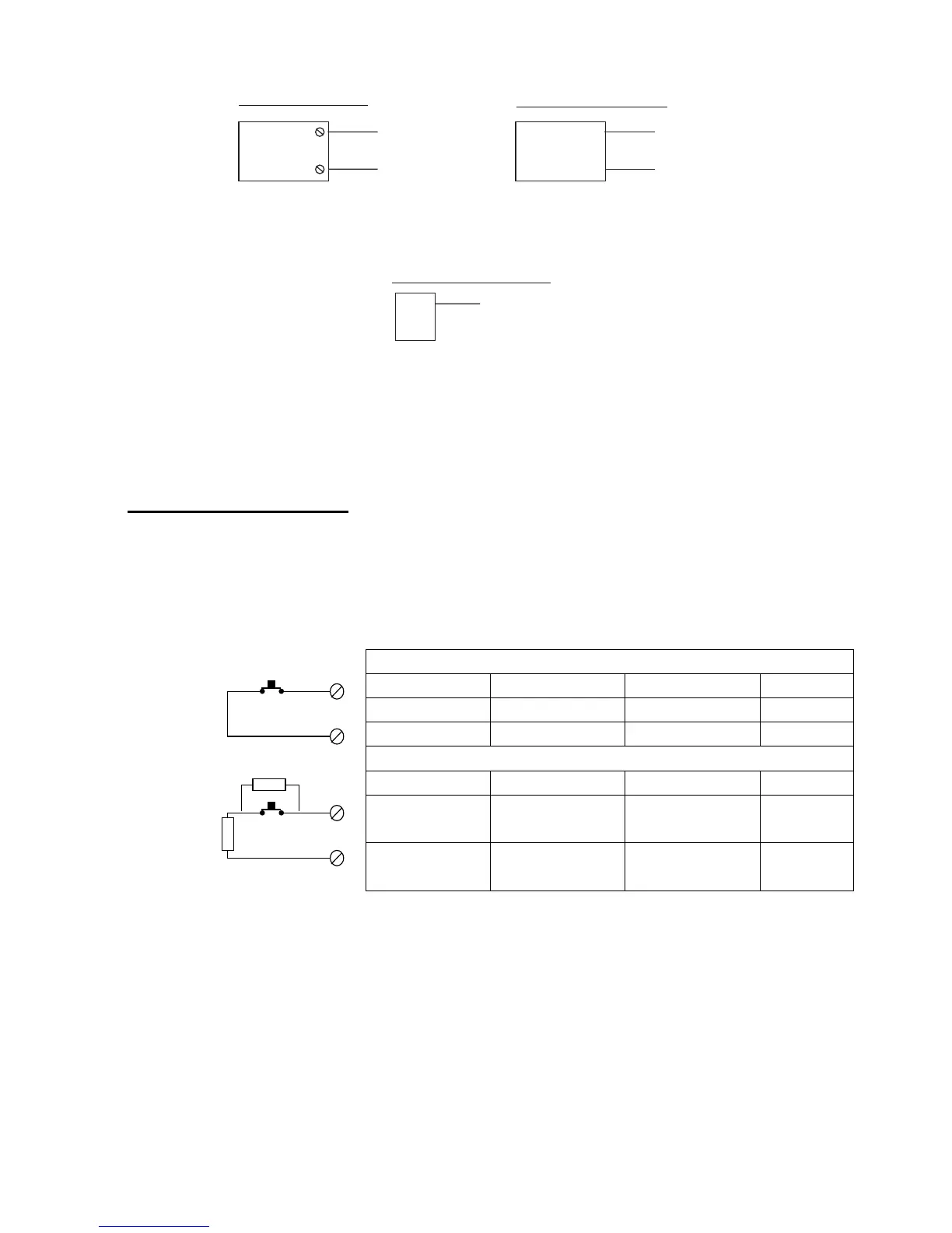
Wiring Keyswitches
To allow a user to set and unset the system using a keyswitch, connect a
fixed position or spring loaded (momentary) key switch to a zone input. When
programming the control unit select zone type (KM) for momentary or (KF) for
fixed position keyswitches. See Command 185 for keyswitch auto-reset.
Figure 21 shows the connections for a keyswitch.
Fixed Keyswitch (KF)
Keyswitch CC FSL System
OFF Closed 2k2 Unset
ON Open 6k9 Set
Momentary Keyswitch (KM)
Keyswitch CC FSL System
Operate Close-Open-
Close
2k2-6k9-2k2 Unset
Operate Close-Open-
Close
2k2-6k9-2k2 Set
Figure 21. Connecting a Keyswitch
Note:
If you connect a keyswitch as a zone it can be used to set and unset the
level to which the zone is assigned.
4k7
2k2
CC Wiring CCT(n)
CCT(n)
FSL Wiring