3. Installation 9751 Installation Guide
Page 26 11976798
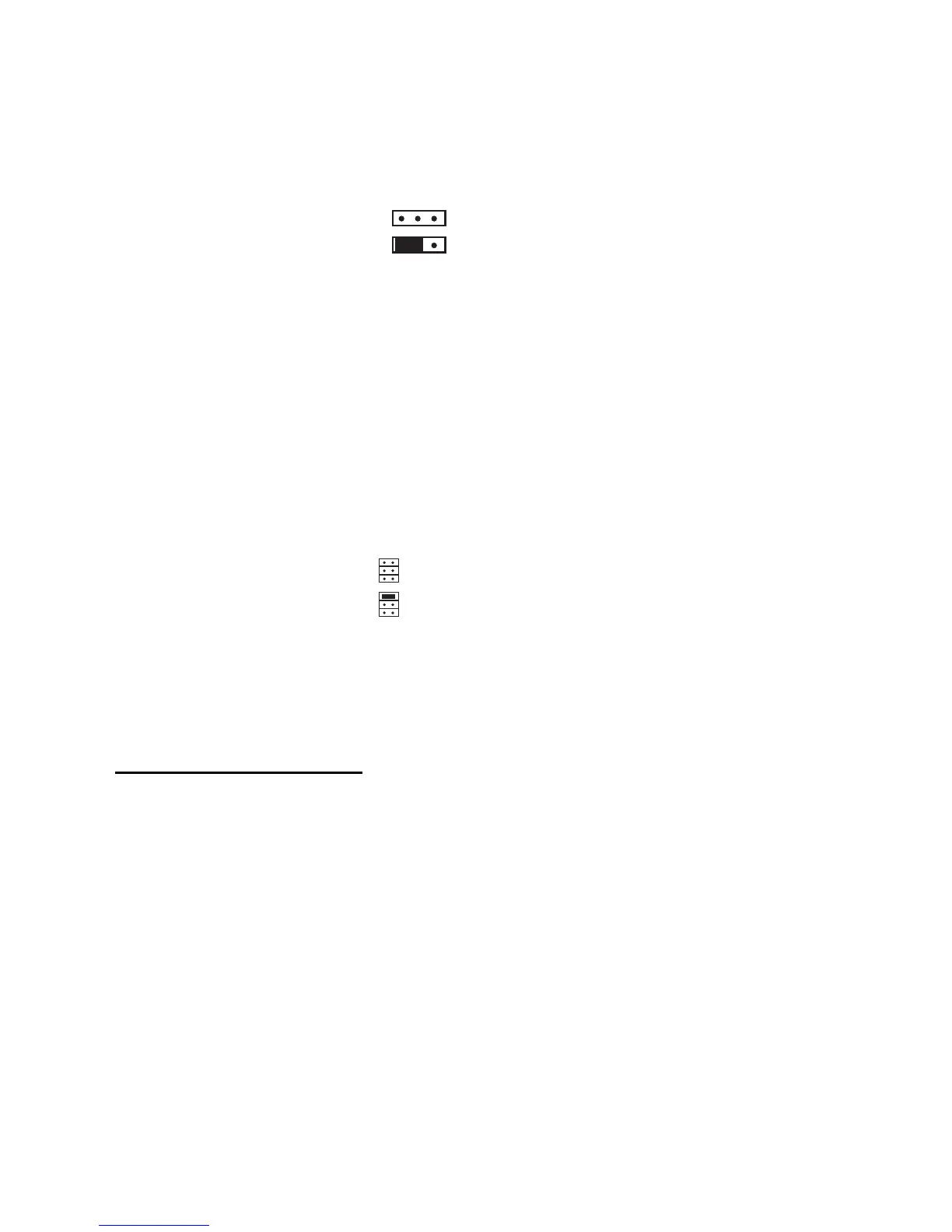
When fitting a 9954 hardwired expander, make sure that you place the jumper
link on the expander in the correct position to select either four-wire CCL, or
two-wire FSL (see Figure 18).
FSL
EOL
Four-wire CC
Two-wire FSL
Figure 18. Link Positions to Select Wiring Method
Once you have connected an expander, refer to the instructions supplied with
it for connecting hardwired detectors or "learning" radio detectors as
appropriate.
Addressing Expanders
If you fit expanders, you must allocate each expander to a specific range of
zone numbers. Do not allocate two expanders to the same range of zones.
Select the zone numbers by fitting a jumper link to one pair of the set of pins
marked "Address" on the expander PCB, as shown in Figure 19.
2
3
4
2
3
4
Zones 9 to 16
Zones 17 to 24
Figure 19. Link Positions to Allocate Expanders to Zones
Note: Other link positions are not valid for the control unit.
Programming Outputs
Control unit outputs can be programmed using the commands shown in the
table below. Open collector outputs are of a "pull down" type that provides
negative-applied control signals; the system adjusts the output polarity when
you select the output type.
Output Type Command
OP1 open collector 81
OP2 open collector 82
OP3 open collector 83
Figure 20 shows some examples of applications for open collector outputs
(OP3 is used in these examples).