38 6 PARTS IDENTIFICATION AND FUNCTIONS
6
6
.
.
2
2
S
S
e
e
t
t
t
t
i
i
n
n
g
g
s
s
a
a
n
n
d
d
L
L
E
E
D
D
I
I
n
n
d
d
i
i
c
c
a
a
t
t
i
i
o
o
n
n
s
s
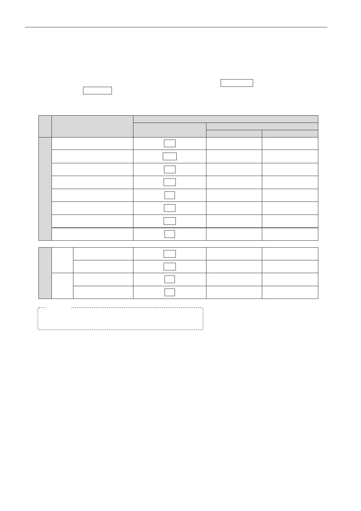
Time and limit settings are displayed as stage symbols on the leak rate indicator.
Alarms are signaled by either the master failure judgement lamp LO NO GO LED or tested part failure
judgement lamp HI NO GO LED blinking together with the stage guidance display to distinguish between a
work setting and a tested part setting.
Stage names and guidance
Stage name
Leak rate indicator
Time settings
Charging delay
dL1
■ ■
Charging
CHG
■ ■
Balancing delay
dL2
■ ■
Balancing bAL ■ ■
Detection
dEt
■ ■
End delay
bL3
■ ■
End
End
■ ■
Stabilization Stb ■ ■
BAL
HI (WORK-side)
bAL
■ □
LO (MASTER-side)
bAL
□ ■
DET
HI (WORK-side)
dEt
■ □
LO (MASTER-side)
dEt
□ ■
In the “Judgement LEDs” columns, □ indicates an off LED,
■ , a blinking LED.