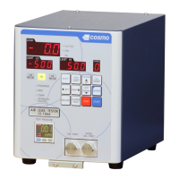
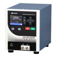
62 10 ORIGINAL (ORG) MODE
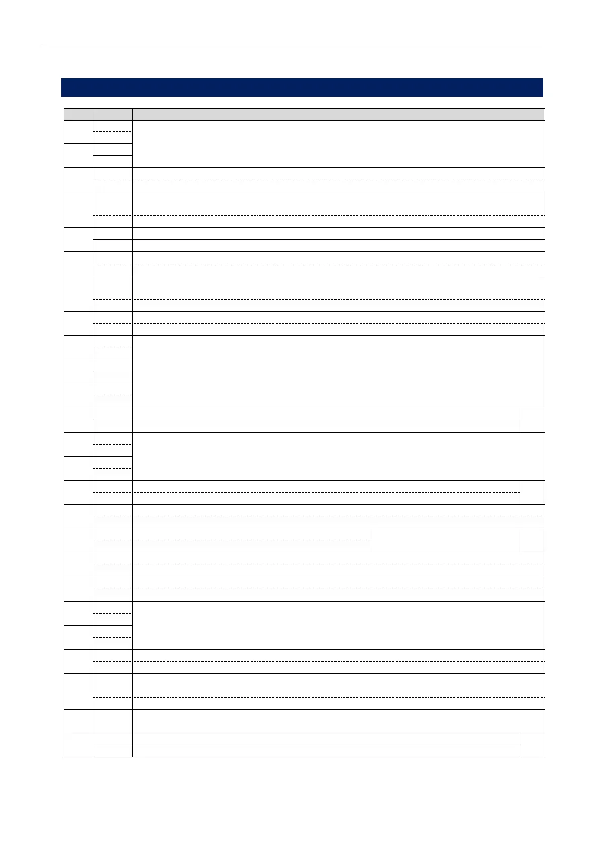
10.2.3 Memory Switch Table
00
DET stage Judgement timing 1)
01
02
External stop: b contact pulse
External stop: a contact pulse
03
0
After the tester makes judgement, the judgement signals are held.
These signals are cleared by the START, STOP or CHG HOLD signals.
The judgement signal is output as pulse.
04
Intelligent I Pneumatic Circuit: AV check will not be performed
Intelligent I Pneumatic Circuit: AV check will be performed
05
Accepts START signal during the END stage.
Does not accept START signal during the END stage.
06
0
Exhaust Interference Prevention is activated.
Tester goes to DL3 and exhausts when START signal is turned off.
Tester goes to DL3 and exhausts right after judgement is made.
07
Offset error is not detected in DL1 stage.
Offset error is detected in DL1 stage.
08
Busy signal (control I/O port pin#36) 2)
09
10
11
±300 Pa for large leak limit in the DL2 stage.
*1
±1000 Pa for large leak limit in the DL2 stage.
12
CHG stage display 3)
13
14
The judgement signal is transmitted at END stage.
*2
The judgement signal is transmitted at DL3 stage.
15
16
Pilot pressure is monitored.
Set to 1 for other than the
pressure switch built-in unit.
*3
Pilot pressure is not monitored.
17
Test pressure is not monitored with upper and lower limits.
Test pressure is monitored with upper and lower limits.
18
19
Serial communication output format selection 4)
20
21
22
0
Test pressures of odd-numbered channels are monitored with OUT1 and even-numbered
channels are monitored with OUT2.
Checks the test pressure only with OUT1of pressure switch.
23
Pressurization valve malfunction 5)
24
Change the maximum values of the CHG timer and the STB timer to 6000 seconds.
*4
Change the maximum values of the CHG timer and the STB timer to 999.8 seconds.
*1 For the micro-pressure specification, large leak may not be large enough for ±1000 Pa. Select ±300
Pa for large leak limit in such cases. If the leak is judged to be large, “999 (-999)” and “HI NO GO (LO
NO GO)” will blink on the LEAK indicator.