12 INTERFACE 67
1
1
1
1
INTERFACE
1
1
1
1
.
.
1
1
C
C
o
o
n
n
t
t
r
r
o
o
l
l
I
I
/
/
O
O
P
P
o
o
r
r
t
t
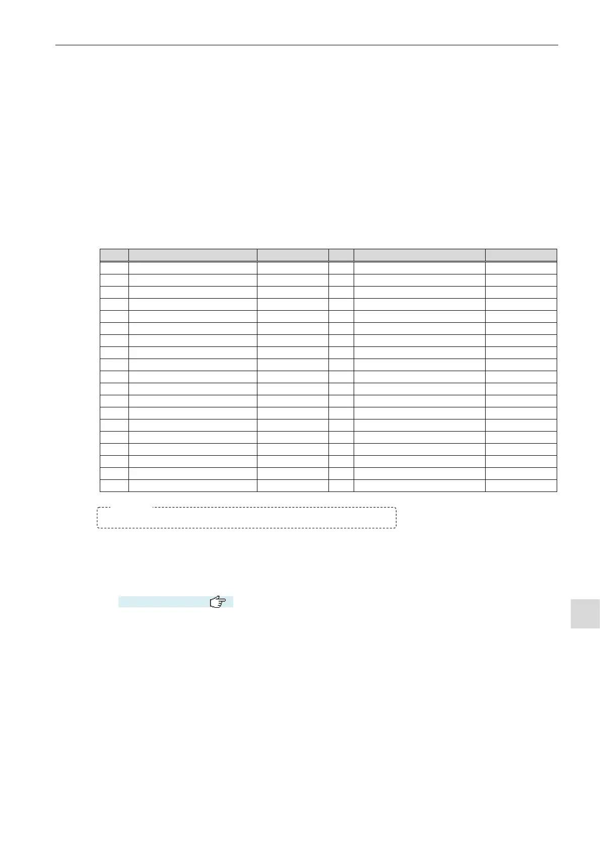
The control I/O port interfaces the tester to an external device such as PLC with the capabilities to control
and receive the test results remotely. This port allows the tester to be integrated into a fully automated line.
a) Connector type:
Leak tester side: DB-37P (XM2C-3712-112 OMRON or equivalent)
Cable side: DB-37S (XM2D-3701 OMRON or equivalent)
b) Connector configuration: NO: Normally open NC: Normally closed
*1 Master-Preset value sampling
*2 Timer extension signal is transmitted at the Noise Reduction process execution, or the
Master-Preset value sampling.
*3 NG judgement signal is transmitted during DL3 and END stages. Signal output can be limited to
END stage, or change the output to a hold signal by memory switch setting.
(See Section 10.2.3 → )
HI-NG: It is output when the tested part limit value HI is exceeded.
HH-NG: It is output when the HI is exceeded by +10% (NR limit). (At this point, also HI-NG is
output.)
LO-NG: It is output when the reference part limit value LO is exceeded.
LL-NG: It is output when the LO is exceeded by +10% (NR limit). (At this point, also LO-NG
is output.)
c) Power supplies
Operational power supplies are required to use the control I/O port.
Rated input voltage: 12 to 24 VDC ±10%, 0.2 A max. (external power supplied by the SELV circuit)
Leave the pins marked “Reserved” in the table above opened.
 Loading...