11 INTERFACE 79
3) P format (serial printer output)
When an inspection ends, the inspection result is printed in the END stage.
: Air-operated valve error
Output example
Press the ENTER key while holding down the SHIFT key to print
memory switch settings and timer limits.
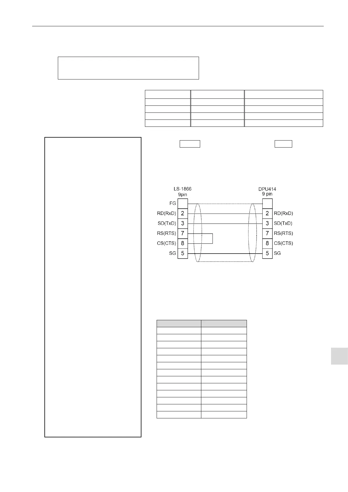
• Recommended printer type: DPU-414 Series
• Seiko’s cable: Straight
Change the printer settings to followings:
CR function = Carriage return
Baud rate = 9600 (bps)
EXTENSION MEMORY SWITCH 23 converts a value (00-34) set
in the default (ORG) mode memory switch setting (P-2) 23 into 1 –
D in hexadecimal notation.
When 11 is set to the memory switch setting (P-2) 23, the output
of the setting is 23-2: WAIT DSP LIMIT.
----------------------------
CH=0 TOTAL COUNT
TOTAL: 0000, GOOD: 0000
HH NG: 0000, Hi NG: 0000
LL NG: 0000, Lo NG: 0000
----------------------------
CH=0 UNIT, LIMIT
LEAK U: [Pa ]
BAL Hi: +650.
BAL Lo: -250.
DET HH: +72.0
DET Hi: +060.
DET Lo: -020.
DET LL: -24.0
NR:02
----------------------------
CH=0 COEF., TIMER
K(Ve): -003.960L
COMP(OFF).: +000.Pa
DL1: +0000.5s
CHG: +0005.0s
DL2: +0001.0s
BAL: +0003.0s
DET: +0003.0s
STB: +0005.0s
DL3: +0000.5s
END: +0000.5s
----------------------------
LEAK MASTER: +29.7mL/min
SPAN GAIN: +001.000
HH/LL RATIO:50%
----------------------------
SYSTEM MEMORY SWITCH
00-1: >
01-1: >AIR CIRCUIT TYPE
02-1: LEAK UNIT
03-1: RESERVED
04-1: >
05-1: >RESERVED
06-1: >
07-1: >DPS RANGE
08-1: >
09-1: >RESERVED
10-0: >
11-1: >
12-1: >
----------------------------
EXTENSION MEMORY SWITCH
00-1: >
01-1: >JUDGE MODE
02-1: EXT STOP a/b
03-0: JUDGE pulse/hold
04-1: AV CHECK in DL3
05-1: NEXT START in END
06-1: EXHAUST
07-1: MONITOR E-OFS in DL1
08-1: >
09-1: >
10-1: >BUSY SIG. TYPE
11-1: LARGE LEAK LIMIT
12-1: >
13-1: >LEAK DISPLAY in CHG
14-1: JDG OUT DL3/END
15-0: HH,LL ratio 10/20
16-1: AV SWITCH CHECK
17-1: TP SWITCH CHECK
18-1:
BAUD RATE
19-1:>
20-0:> COM FORMAT
21-1:
NOP
22-1: TPsw2 ON/OFF
23-2:
WAIT DSP LIMIT