EasyManua.ls Logo

Cosmos PS-7 - User Manual

Cosmos PS-7
60 pages
Print Icon
To Next Page IconTo Next Page
Loading...
New Cosmos PS-7
User Manual
Includes:
Product Manual
Administrator Manual
Pyrolyzer Manual

Other manuals for Cosmos PS-7

Questions and Answers

  • G
    gutierrezpeterAug 9, 2025
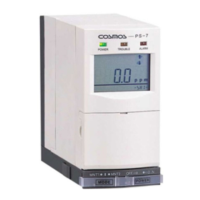
    How to fix POWER lamp (green) if it does not come on for Cosmos Gas Detectors?
    • C
      Christy SmithAug 9, 2025
      If the POWER lamp (green) does not come on when you turn on your Cosmos Gas Detectors, there are several potential causes. Ensure that the power switch on both the base unit and the main unit are turned ON. Check the wiring to make sure it is properly connected, and tighten the terminal connections if needed. Also, verify that the connector harness is correctly attached. If none of these steps work, the fuse may have blown, and you should replace it.
  • M
    Mark HillAug 15, 2025
    What to do if there is no electrical output from the alarm contacts in Cosmos Gas Detectors?
    • Q
      qyangAug 15, 2025
      If there is no electrical output from the alarm contacts on your Cosmos Gas Detectors, it might be because the device is set to either maintenance mode 1 or 2. To fix this, set the device to normal mode (center). Also, check the wiring to ensure it is properly connected, and tighten the terminal connections if necessary.
  • D
    davidwilliamsAug 21, 2025
    What does it mean when “__” indication and gas concentration value blink alternately on Cosmos Gas Detectors?
    • R
      Rebecca PerezAug 21, 2025
      If the “__” indication and the detected gas concentration value blink alternately on your Cosmos Gas Detectors, it means the device is set to either maintenance mode 1 or 2. To resolve this, set the device to normal mode (center).
  • J
    James ScottAug 27, 2025
    Why analog output won’t change from 4mA on Cosmos Gas Detectors?
    • E
      Emily RandallAug 27, 2025
      If the analog output won’t change from 4mA on your Cosmos Gas Detectors, it is likely that the maintenance switch is set to 2. To correct this, set the switch to normal mode (center).
  • M
    Manuel SwansonNov 2, 2025
    Why is the TROUBLE lamp (yellow) blinking on my Cosmos Gas Detectors?
    • H
      Haley BoothNov 2, 2025
      If the TROUBLE lamp (yellow) is blinking on your Cosmos Gas Detectors, it could be due to several reasons. First, the filter element might be clogged, in which case you should replace it. Alternatively, the pump may be defective, requiring you to replace the pump unit. A blocked gas sampling pipe could also be the cause; remove the blockage to resolve this. Ensure the connector harness is properly connected by checking and reattaching it if necessary. A sensor with incorrect settings may have been inserted; adjust the settings on the main unit or replace the sensor. A defective sensor unit should be replaced. Ensure the sensor unit is correctly installed. Finally, if the flow sensor output was unstable when the power was turned on, leave the power on for about 30 minutes to allow it to sta...

Summary

Chapter 1 - Introduction

1.1 Explanation of Symbols

This manual uses symbols. Their meanings must be understood for safe operation.

Chapter 2 - Safety Instructions

Chapter 3 - Contents of This Package

3.1 End of Line Filter Use

Details the use of different end-of-line filters for various gases.

Chapter 4 - System Flow Diagram

Chapter 5 - Description

5.1 Components on the Main Unit

Identifies and describes the components located on the main unit of the PS-7 detector.

5.2 Details of the Key Switch Section

5.3 Details of the LCD Screen Display

Chapter 6 - Installation and Wiring

6.1 Installing the Main Unit

Provides step-by-step instructions for mounting and securing the main unit.

6.2 Wiring Instructions

Details the terminal board connections and their functions for wiring the unit.

Chapter 7 - Operation

7.1 Operation Procedures

Outlines the sequential steps for initial setup and operation of the gas detector.

7.2 Gas Alarm Operating Instructions

Explains how the gas alarm functions, including lamp indicators and LCD displays.

7.3 Trouble Alarm Operating Instructions

Details conditions that activate the trouble alarm and their corresponding indicators.

7.4 Test Mode Settings and Operating Instructions

Covers how to enter and operate the test mode for the gas detector.

7.5 Maintenance Mode Settings and Operating Instructions

Explains the settings and operations for maintenance modes 1 and 2.

Chapter 8 - Maintenance and Inspection

Frequency and Content of Inspections

Provides a timetable for periodic inspections of the gas detector components.

Chapter 9 - replacing Consumables

9.1 Replacing the Filter Element (FE-1)

Step-by-step guide for replacing the filter element if it becomes dirty or clogged.

9.2 Attach;Replacing the Sensor Unit

Instructions for safely attaching or replacing the sensor unit of the detector.

9.3 Replacing the Sampling Unit

Guidance on how to safely replace the sampling unit of the gas detector.

Chapter 10 - Troubleshooting

Chapter 11 - Specifications

Chapter 12 - Warranty

Chapter 13 - Detection Principles

13.1 Electrochemical Sensor

Explains the detection principle of the electrochemical sensor used in the unit.

13.2 Hot-wire Semiconductor Sensor

Describes the detection principle of the hot-wire semiconductor sensor.

13.3 Galvanic Cell Sensor

Explains the detection principle of the galvanic cell sensor.

Chapter 14 - Glossary

Administrator Manual

Chapter 1 - Passwords

1.1 Password Protected Settings

Identifies settings that are protected by a password and require unlock.

1.2 Releasing the Password Lock

Details the procedure to release the password lock on the unit.

Chapter 2 - Changing Settings

2.1 Span Adjustment

Step-by-step guide to perform span adjustment for specific sensor types.

2.2 21 Vol% Adjustment

Instructions for adjusting the 21 Vol% setting for the oxygen sensor unit.

2.3 Changing Setting Values

Explains how to modify various configurable setting values on the unit.

2.4 Changing the Alarm Settings

Guides on how to modify alarm levels and settings for the gas detector.

Pyrolyzer Manual

Chapter 1 - Attach;Replacing the Pyrolyzer

Cosmos PS-7 Specifications

General IconGeneral
Detection GasH2S
Detection PrincipleElectrochemical sensor
Alarm set value10 ppm
Response TimeWithin 30 seconds
Operating Temperature-20°C to 50°C
Operating Humidity10 to 90% RH (non-condensing)

Related product manuals