45
DC-ITD-PS7MAN01.A www.dodtec.com
JAN 2019 815-788-5200
Chapter 11 – Specifications
Electrochemical sensor, hot-wire semiconductor sensor, galvanic cell sensor
Pump suction type (0.5 L/min, suction flow automatically controlled)
Teflon OD6/ID4 mm, maximum tube length 20 m.
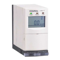
4-digit digital LCD display(incl. units)20-segment bar graph
• Combustible gas 25% of preset alarm point under identical conditions
• Toxic gas 30% of preset alarm point under identical conditions
• Oxygen deficiency 1 vol% under identical conditions
• Combustible gas Within 30 secs using test gas concentration 1.6 times that of preset alarm point
• Toxic gas Within 60 sec. using test gas concentration 1.6 times that of preset alarm point
• Oxygen deficiency Within 5 sec. to reach 18 vol% reading (at 20 2C) from an atmosphere
concentration of 10 vol%
(Gas sampling pipe length and communication times not included in any of the above.)
• Gas alarm (1
st
and 2
nd
stage)
ALARM lamp (red) blinking: LCD display ALARM1 or ALARM2 is displayed
• Trouble alarm
Decreased rate of flow
TROUBLE lamp (yellow): LCD display FLOW displayed: The flow rate rotation is stopped
Sensor trouble
TROUBLE lamp (yellow) blinking: LCD display SENS. is displayed
The sensor unit is inserted incorrectly
TROUBLE lamp (yellow): LCD screen SENS. is displayed
Pyrolyzer is disconnected
TROUBLE lamp (yellow) blinking: LCD screen CONV. is displayed
• Analog output
4-20mA DC (common negative with power supply)
*Resistance for detecting current to be less than 300Ω including circuit resistance.
• Alarm contacts (1
st
and 2
nd
stages)
1a no-voltage contact/auto reset
*Rated load: 125 V AC or 30 V DC, 0.5-A resistance load
• Trouble alarm
Open collector/auto return/auto reset
(Normal close: Normally ON, during trouble OFF, and OFF during shut-off of power supply.
*Rated load: 30 V DC, 30mA resistance load
Activated by decline of flow rate, sensor error, when the sensor unit has been inserted incorrectly, pyrolyzer
is disconnected, power off, or blown fuse.
The analog output is smaller than 0.6 mA, and the gas alarm is not activated.
Shielded control cable (8 to 11 mm dia.) x2
Maximum length not exceeding 500 m
0-40C (avoid radical temperature fluctuation), 30-85% RH (no dew condensation)
Approximately7 W (Approximately 10 W with convertor attached)
W62 H124 D143 mm (projected portion excluded)