9
DC-ITD-PS7MAN01.A www.dodtec.com
JAN 2019 815-788-5200
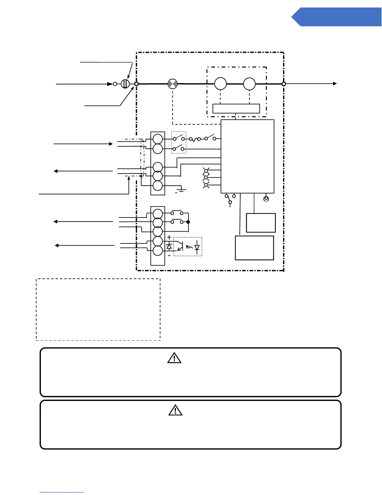
Chapter 4 – System Flow Diagram
Figure 1 System flow diagram
1st level warning
2nd level warning
Common
Trouble
warning
Warning contact capacity (ZA1orZA2-ZC)
(Rated load: 125 V AC or 30 V DC
0.5-A resistance load)
Trouble output (TA-TC)
(Rated load: 30 V DC 30-mA
resistance load)
Gas alarm contact output
(N/O)
(4-conductor shielded cable)
Analog Output
4 to 20 mA DC
Trouble warning output
(N/C)
Warning
Pay special attention to the polarity of the trouble warning output. As the circuit protection
diodes are internalized, if the polarity is reversed, the trouble warning 1 Pull back
not be output.
Caution
The analog output source is not insulated from the power source. In case it is used in
combination with other types of devices, the analog signal must be isolated from flowing into
the power sources of the other devices.