44
DC-ITD-PS7MAN01.A www.dodtec.com
JAN 2019 815-788-5200
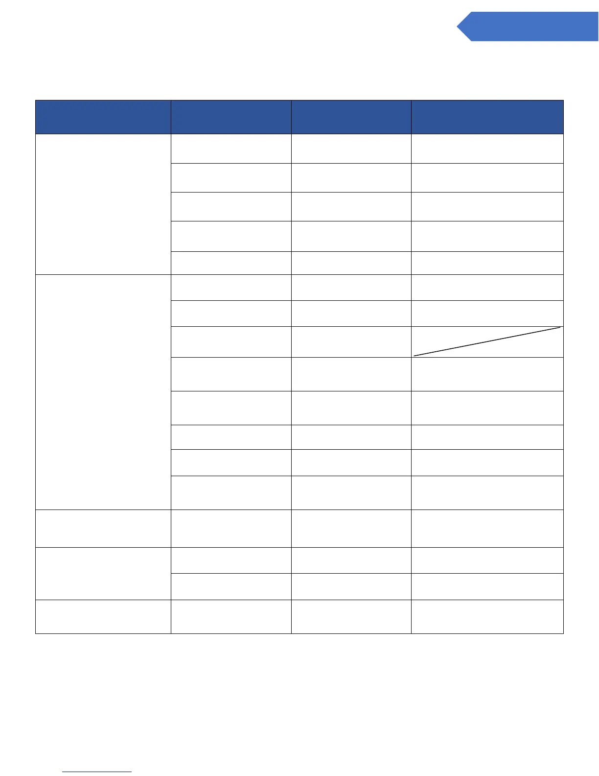
Chapter 10 – Troubleshooting
If a problem occurs, check the following before contacting a service or sales representative.
The POWER lamp (green) does not
come on when the power is turned
on
The power switch on the base
unit is turned OFF.
Turn the power switch to the
base unit ON.
The power switch on the main
unit is turned OFF.
Turn the power switch to the
main unit ON.
Wiring is not properly
connected.
Check wiring and tighten
terminal connections.
The connector harness is not
connected properly.
Check and reattach the
connector.
9.3 Replacing the Sampling Unit
The TROUBLE lamp (yellow) is
blinking
The filter element is clogged.
Replace the filter element.
9.1 Replacing the Filter Element FE-1
9.3 Replacing the Sampling Unit
Gas sampling pipe is blocked.
The connector harness is not
connected properly.
Check and reattach the
connector.
9.3 Replacing the Sampling Unit
A sensor with different setting
has been inserted.
Change the settings on the
main unit or change the
sensor.
9.2 Attach/Replacing the Sensor Unit
Sensor unit is not installed.
9.2 Attach/Replacing the Sensor Unit
The output of the flow sensor
was not stable when power
was turned on.
Turn the power on and leave
for about 30 minutes until it
stabilizes.
The “__” indication and the detected
gas concentration value blink
alternately.
It is set to either maintenance
mode 1 or 2.
Set to normal mode (center).
7.5 Maintenance Mode Settings and
Operating Instructions
There is no electrical output from
the alarm contacts.
It is set to either maintenance
mode 1 or 2.
Set to normal mode (center).
7.5 Maintenance Mode Settings and
Operating Instructions
Wiring is not properly
connected.
Check wiring and tighten
terminal connections.
The analog output won’t change
from 4mA.
The maintenance switch is set
to 2.
Set to normal mode (center).
7.5 Maintenance Mode Settings and
Operating Instructions
Contact your local dealer if none of the above procedures remedy the problem or if the problem is not listed.