10
DC-ITD-PS7MAN01.A www.dodtec.com
JAN 2019 815-788-5200
Chapter 5 – Description
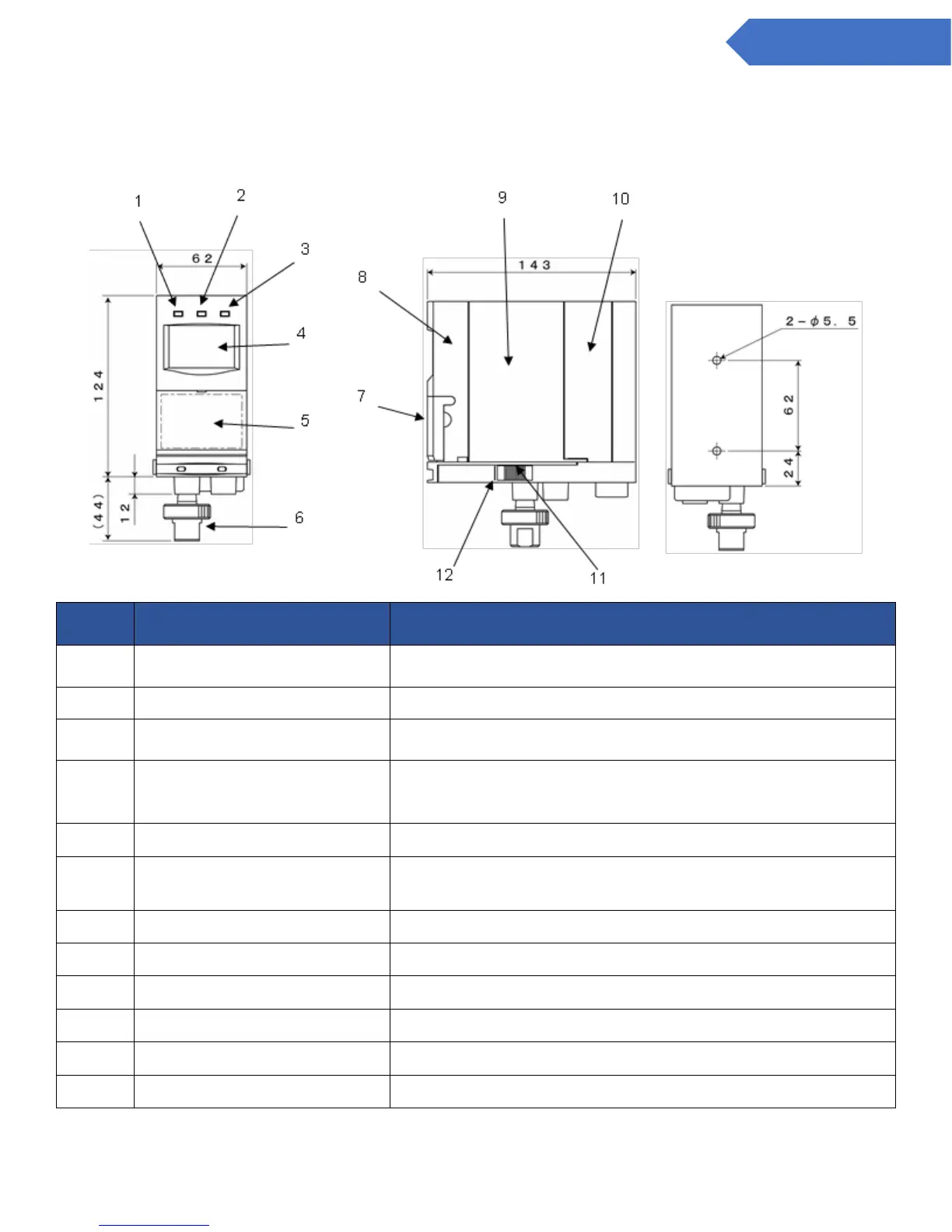
5.1 Components on the Main Unit
(Green) Power lamp. Illuminates during regular monitoring
operations.
(Yellow) The lamp blinks when trouble occurs.
(Red) The lamp blinks when the concentration level of detected
gas exceeds that of the preset alarm level.
Warning displays, detected gas levels, bar graphs of gas levels,
trouble states, maintenance modes, test mode, flow sign are all
shown on the LCD display.
Switches to carry out the various settings.
Incorporates a filter element (FE-1) that prevents dust from
entering the gas inlet and tubes leading to the sensor.
Lift up gently to use key switches.
The pump is contained inside the sampling unit.
The cover protecting the sensor unit.
Latches to attach the main unit onto the base unit.
A line (mark) to show the return position of the latch.
 Loading...