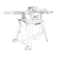
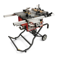
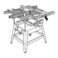
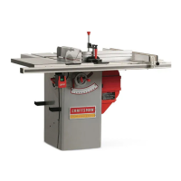
OPERATING COMPONENTS
The upper portion of the blade projects up through the
table and is surrounded by an insert called the throat
plate. The height of the blade is set with a handwheel on
the front of the cabinet. To accommodate wide panels,
the saw table has rails on each side. Detailed instructions
are provided in the Operation section of this manual for
the basic cuts: cross cuts. miter cuts, bevel cuts. and
compound cuts.
The rip fence is used to position work for lengthwise cuts.
A scale on the front rail shows the distance between the
rip fence and the blade,
it is very important to usa the blade guard assemblyfor all
through-sawing operations. The blade guard assembly
includes: riving knife/spreader/splitter, anti-kickback
pawls, and plastic blade guard.
POWER SWITCH
This saw is equipped with a power switchthat has a
built-in locking feature. This feature is intended to prevent
unauthorized and possible hazardous use by childrenand
others,
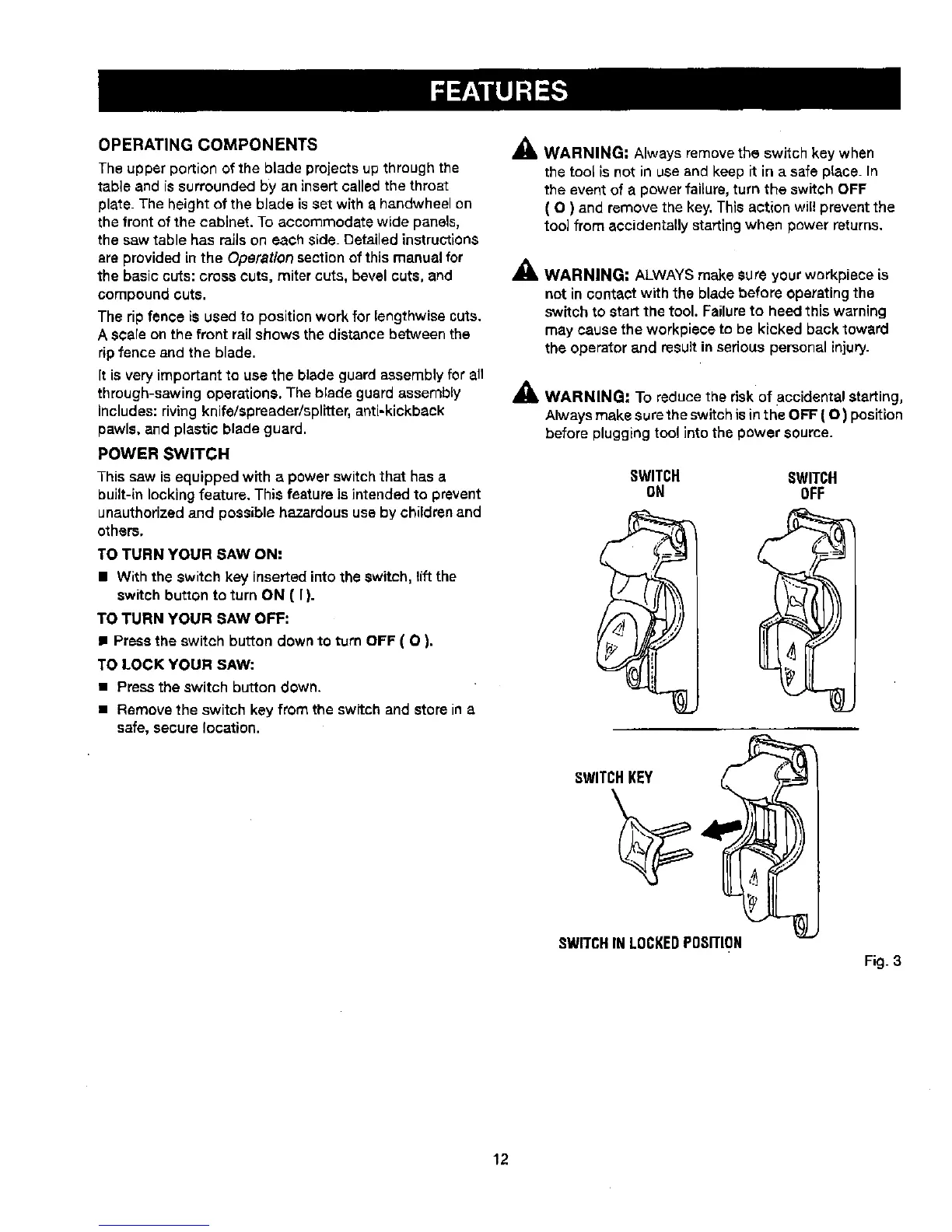
TO TURN YOUR SAW ON:
• With the switch key insertedinto the switch, lift the
switch button to turn ON ( I ).
TO TURN YOUR SAW OFF:
• Press the switch button down to t_rn OFF ( O ).
TO LOCK YOUR SAW:
• Press the switch button down.
• Remove the switch key from the swftchand store in a
safe, secure location.
_k WARNING: Always remove the switch key when
the tool is not in use and keep it in a safe place. In
the event of a power failure,turn the switch OFF
( O ) and remove the key, This action will prevent the
too] from accidentally starting when power returns.
_, WARNING: ALWAYSmake sure your workplace is
not in contact with the blade before operatingthe
switch to startthe tool. Failureto heed this warning
may cause the workpiece to be kicked backtoward
the operatorand result in seriouspersonal injury.
_lb WARNING: To reduce the riskof accidental starting,
Always makeaurethe switch isinthe OFF (O) position
before plugging tool into the power source.
SWITCH SWITCH
ON OFF
SWITCH,KEY ,,__
SWITCHIN LOCKEDPOSITION
Fig. 3
12
 Loading...