EasyManua.ls Logo

Crouzet CTR48 Series - User Manual

Crouzet CTR48 Series
106 pages
Go to English
Print Icon
To Next Page IconTo Next Page
Loading...
Contatore elettronico a
preselezione con due
preselezioni
Esecuzioni
LCD positivo
LCD positivo, retroilluminazione verde
LCD negativo, retroilluminazione rossa
LCD negativo, retroilluminazione verde-
rossa
Contador electrónico de
preselección con dos
preselecciones
Modelos
LCD positivo
LCD positivo, retroiluminación verde
LCD negativo, retroiluminación roja
LCD negativo, retroiluminación verde-
roja
Elektronischer Vorwahlzähler
mit zwei Vorwahlen
Ausführungen
LCD positiv
LCD positiv, grün hinterleuchtet
LCD negativ, rot hinterleuchtet
LCD negativ, rot-grün hinterleuchtet
françaisenglishitaliano
español
deutsch
Notice de mise en service
Compteur électronique à afficheur
CTR48
R.60318.9451
Compteur à présélection
électronique avec deux
présélections
Versions
LCD positif
LCD positif, rétroéclairage vert
LCD négatif, rétroéclairage rouge
LCD négatif, rétroéclairage rouge-vert
Electronic Preset Counter
With two presets
Models
LCD positive
LCD positive, green backlighting
LCD negative, red backlighting
LCD negative, red-green backlighting
www.hvssystem.com
Siège social :
2 rue René Laennec
51500 Taissy
France
Contact :
hvssystem@hvssystem.com
Tél : 0326824929
Fax : 0326851908
Distribué par :

Table of Contents

Question and Answer IconNeed help?

Do you have a question about the Crouzet CTR48 Series and is the answer not in the manual?

Crouzet CTR48 Series Specifications

General IconGeneral
SeriesCTR48
Display TypeLCD
Number of Digits8
Reset TypeManual
Power SupplyAC
FunctionsCounting, Batch

Summary

Crouzet CTR48 Electronic Counter

Product Overview and Versions

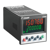
Details the electronic preset counter CTR48 and its available versions.

Safety and Installation

Safety Instructions and Intended Use

Covers essential safety precautions, intended purpose, and operational warnings for the device.

Mounting and Electrical Installation Guidelines

Provides instructions for mounting the device in a control panel and safe electrical installation.

Display and Control Elements

Key Functions and Display Indicators

Explains the function of each key and the meaning of various display indicators on the CTR48.

Inputs and Outputs

Signal Input Configurations

Details the functions of signal inputs INP A, INP B, RESET, and GATE for different operating modes.

Output Configuration Options

Describes the types of outputs (relay, transistor) and their configurations, including active outputs.

Counter Programming

Navigating and Entering Programming Modes

Guides users through entering, selecting menus, and setting parameters within the programming interface.

Programming Menu Structure

Factory Settings and Basic Function Selection

Details how to reset to factory settings and select the basic function (Pulse Counter, Timer, etc.).

Pulse Counter Output Operations

Main Output Operation Modes for Pulse Counting

Explains various output operations for pulse counting, including count modes and reset behaviors.

Pulse Counter Signal Inputs

Signal and Control Input Configurations

Details input polarity, filters, and input modes for pulse counting operations.

Timer Functions

Timer Configuration and Display Settings

Covers time units, decimal point settings, and display color options for timer functions.

Timer Output Operations and Reset Modes

Explains output operations and reset modes applicable to timer functions.

Tacho;Frequency Meter Inputs

Signal Input Configuration for Frequency Measurement

Details input configurations, filters, and measurement modes for tacho/frequency meter functions.

Tacho;Frequency Meter Configuration

Measurement Modes and Display Options

Covers total measurement, frequency measurement, and display settings for the Tacho/Frequency meter.

Preset 1 Management

Preset 1 Configuration and Output Logic

Details settings for Preset 1, including ON/OFF control, output logic, and pulse duration.

Preset 2 Management

Preset 2 Configuration and Output Logic

Details settings for Preset 2, including ON/OFF control, output logic, and pulse duration.

Programming Lock and Presets Setting

Main Programming Lock Menu

Explains how to lock and unlock programming access for presets.

Setting Presets via Decade Keys

Describes the method for setting preset values using decade keys.

Connections

Terminal Connections Overview

Illustrates terminal layout for supply voltage, outputs, and signal/control inputs.

General Technical Data

Display, Counter, Tacho;Frequency, Timer Specifications

Provides key technical data for display, pulse counter, tacho/frequency meter, and timer functions.

Device Specifications

Supply Voltage, Safety, and Environment

Covers supply voltage ranges, device safety standards, environmental conditions, and EMC compliance.

Mechanical, EMC, and Connections Specs

Details mechanical data, EMC characteristics, and connection terminal specifications.

Scope of Delivery and Ordering

Product Scope and Ordering Code

Lists the items included in the scope of delivery and explains the ordering code structure.

Frequency Specifications

Details pulse counter and frequency meter frequency specifications.

Pulse Counting Input Modes

Pulse Counting Input Mode Details

Explains various input modes for pulse counting, including direction and preset behavior.

Timing Input Modes

Timing Input Mode Configurations

Details the different input modes for timing functions, including start/stop triggers and gate input.

Frequency Meter Input Modes

Frequency Meter Input Mode Details

Explains input modes for frequency meter functions, covering single, differential, and total measurements.

Output Operation Diagrams

Output Diagrams for Modes rS0 to tCrSA2

Visual representations of output behavior for various pulse counter modes.

More Output Operation Diagrams

Output Diagrams for Modes bCrS0 to MurS0

Visual representations of output behavior for additional pulse counter modes.

Device Dimensions

Physical Dimensions and Panel Cutout

Provides the physical dimensions of the CTR48 and the required panel cutout dimensions.

Related product manuals