41
L510023-07
Attaching/Adjusting Shift Cable - Velvet Drive
5000 Series Transmissions
These model transmissions are full reversing
transmissions. Rotation of the output fl ange and
propeller shaft is determined by the hookup of the shift
cable at the remote control before starting the installation
and adjustment procedures.
For left-hand (LH) shaft rotation - the transmission shift
lever must move TOWARD the engine (fl ywheel) when
the remote control shift handle is placed in the forward
position.
For right-hand (RH) shaft rotation - the transmission shift
lever must move AWAY from the engine (fl ywheel) when
the remote control shift handle is placed in the forward
position.
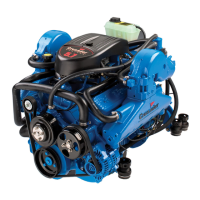
Figure 45 Typical Shift Cable Installation
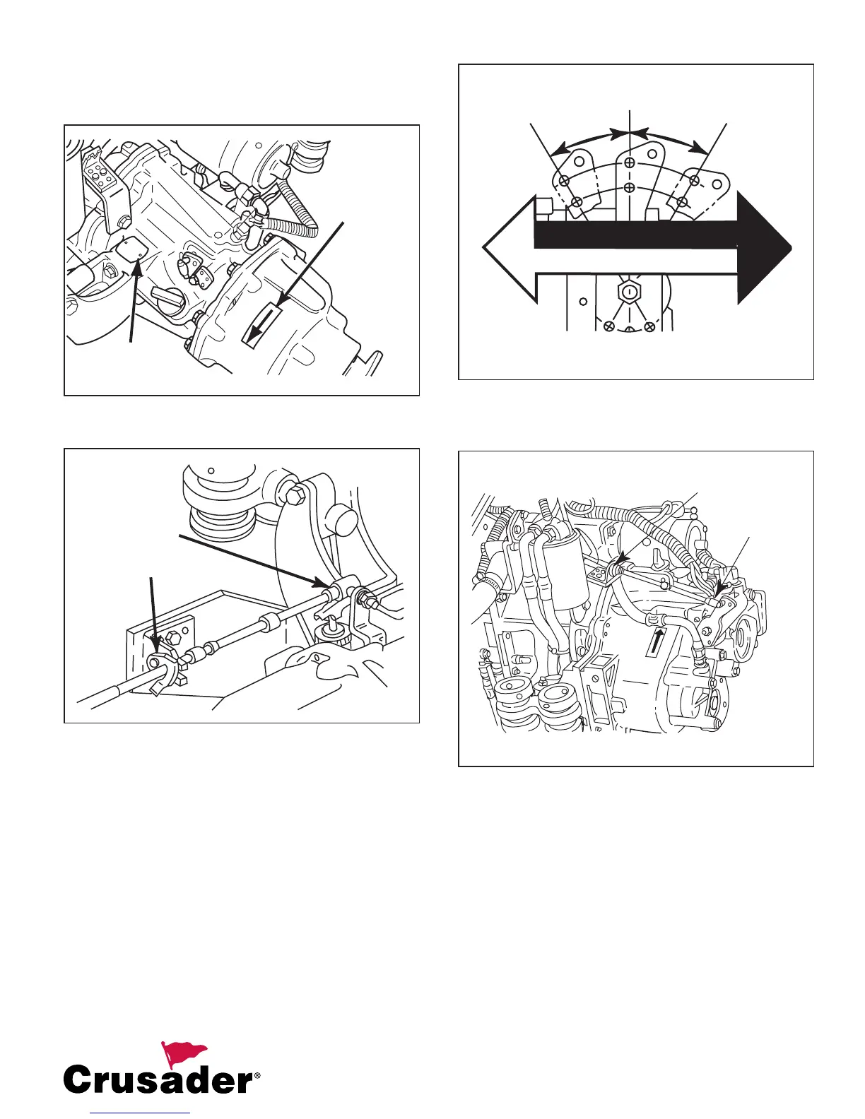
Figure 46 Velvet Drive 5000 Shift Lever Movement vs.
Output Flange Rotation
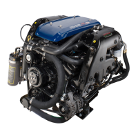
Figure 47 Shift Cable Installation - Velvet Drive 5000
1. Place the remote control shift lever and
transmission shift lever in neutral position.
2. Install the shift cable hub into the shift cable
retaining bracket and lock the cable clip.
3. Thread the clevis pin onto the shift cable until
the clevis lines up with the stud attached to the
transmission shift lever.
4. Retract the spring lock on the clevis pin and
attach the shift cable to the ball joint stud.
LH
RH
FORWARD
GEAR
FORWARD
GEAR
VELVET DRIVE 5000
TRANSMISSIONS
RH PROP SHAFT ROTATION
LH PROP SHAFT ROTATION
CABLE CLIP
BALL JOINT
BALL JOINT
CABLE CLIP
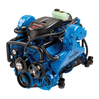
Figure 44 Forward Gear Prop Shaft Rotation - Standard
Velvet Drive
PROP SHAFT
ROTATION
DECAL
IDENTIFICATION
TAG
8. Shift remote control lever from forward to
reverse and make sure cable moves freely and
no binding occurs.