EasyManua.ls Logo

CS-Lab CSMIO/IP-M

CS-Lab CSMIO/IP-M
69 pages
To Next Page IconTo Next Page
To Previous Page IconTo Previous Page
Loading...
4. Connectors, controls and electrical installation of the device
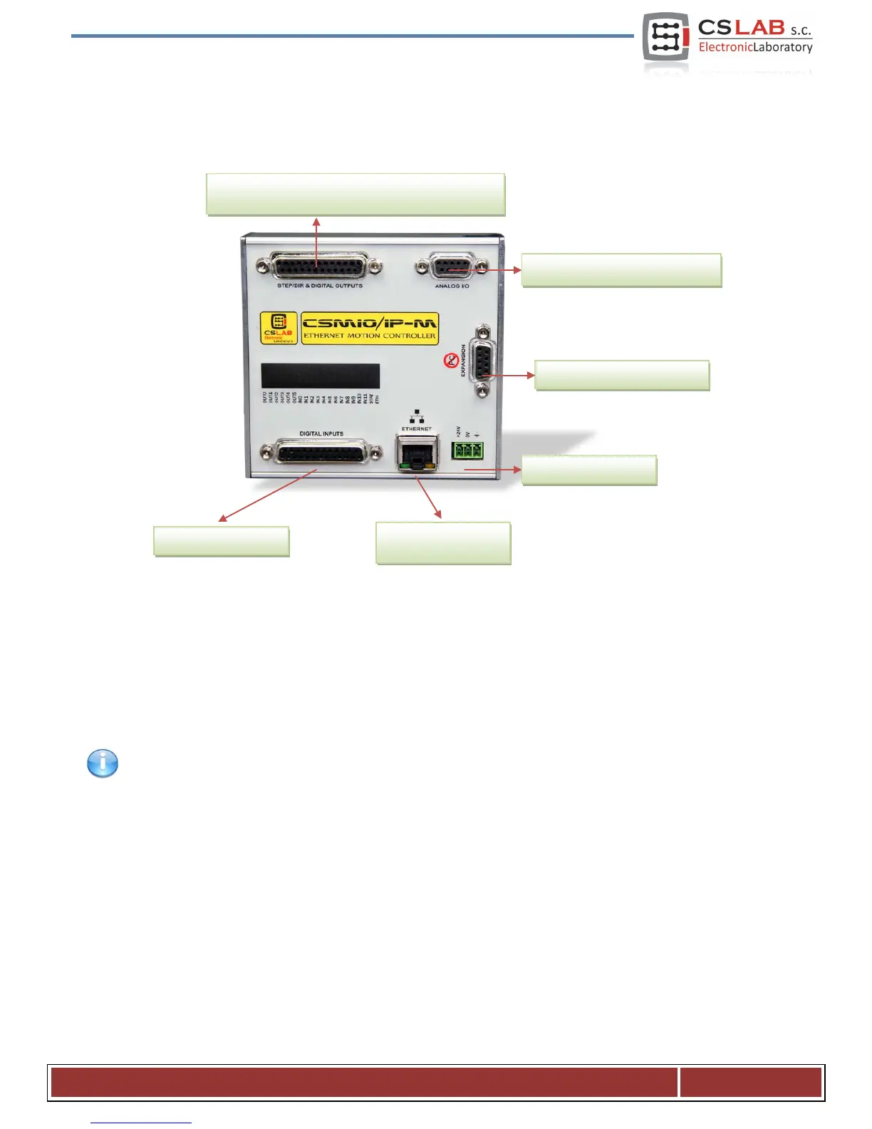
4.1 Arrangement of the connectors on the device
Detailed description of signals on individual connectors is in the following section.
DB->Terminal block modules have the same pin numbers as DB connectors in CSMIO/IP-M device.
For example: the 15 pins of DB25 connector match with the 15 pins on the terminal block.
Signals that control the drives (STEP/DIR)
and digital outputs (relays etc.)
Analog inputs and outputs (0-10V)
Expansion module connector
Power connector
CS- Lab s.c. CNC CSMIO/IP- M controller
Page 10

Table of Contents

Related product manuals