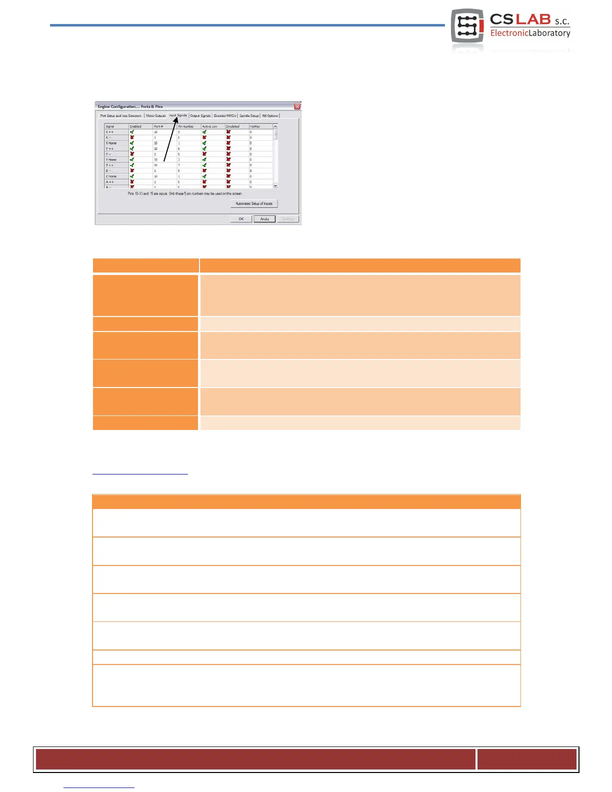
10.4 Configuration of the digital input signals
Configuration of the input signals is selected in the
„Config” menu, the
„Ports and Pins” position, by selecting the
„Input Signals” tab. The list of the standard input
signals will appear and you can assign these signals
to the hardware inputs of the CSMIO/IP-M
controller.
• Green tick means we use the signal.
• Red “X” means that we do not use the signal and that it should not be
Input port number – for the CSMIO/IP-M it is port no. 10.
Pin number, means the CSMIO/IP-M input number, e.g. input no. 5 of the
controller we give here as the pin no. 5.
Changing the polarity of the signal, it is a choice – whether the signal should
be active at 0V or at 24V.
Signal emulation by keyboard shortcut. In the CSMIO/IP-M controller, only
some signals may be emulated: „THC On”, „THC Up”, „THC Dn” and „Probe”.
Keyboard shortcut for the signal emulation.
Detailed description of the signals are available in the documentation on the ArtSoft® website:
www.machsupport.com, below we present short description of the most important ones.
X++, Y++, Z++, A++, B++, C++
Signals of hardware positive limits. The machine stops immediately
when one of the signals becomes active.
X--, Y--, Z--, A--, B--, C--
Signals of hardware negative limits. The machine stops immediately
when one of the signals becomes active.
X Home, Y Home, Z Home,
A Home, B Home, C Home
Input signals for general use. They can be used in the VisualBasic®
scripts.
Signals of the measurement probe, such as tool length measurement
sensor.
The spindle index for the rotational/threading speed measurement.
Motion forcing, if one of the LIMITS signals is active. It is useful to
ride off from the limit switch. If we are using the Auto Limit
Override function – this signal is useless.
CS- Lab s.c. – CNC CSMIO/IP- M controller
Page 38
 Loading...