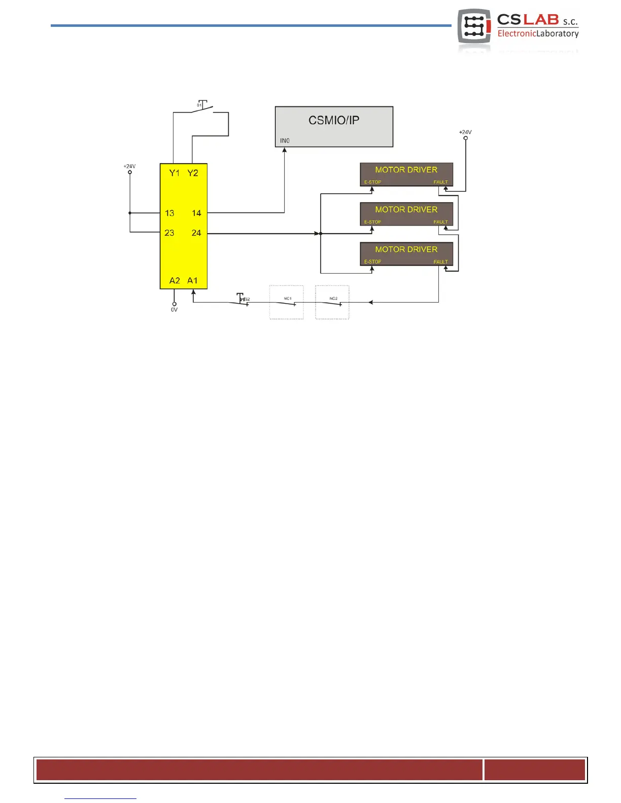
2.1 Example of E-STOP signal connection
The simple example above shows the E-Stop signal connection to the CSMIO/IP-M controller and to the
axis drives, using a Pilz company safety relay (PNOZ X7 24V). S1 is a reset button (safety relay switching
on), S2 is an emergency stop.
This module has one input with all the alarm sources connected to this input (A1). In addition to the
mentioned emergency stop (S2) there are NC contacts - NC1 and NC2, which may be, i.e. opening sensors
for the cover and the control cabinet. Moreover, there are drives’ FAULT signals connected in series. Two
outputs of the safety relay were used as an E-Stop signal for the CSMIO/IP-M controller and axis drives.
This combination assures the machine stops in case of failure
on any axis (FAULT signals of the drives),
by pressing emergency stop mushroom and opening the cabinet or cover. Separation of the safety relay
output channels gives double protection for the system and significantly increases the reliability of the
entire system.
 Loading...