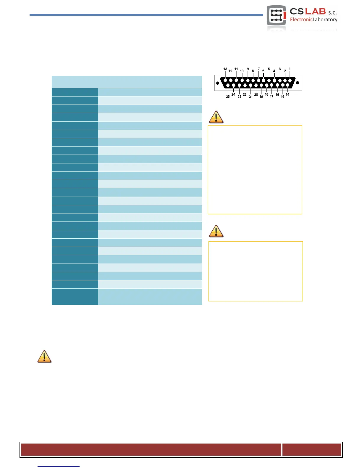
4.2 STEP/DIR controlling signals and digital outputs connector
While connecting the STEP/DIR signals to the motor drive (both servo and stepper drives) pay attention to
which STEP edge is active. The active edge in the CSMIO/IP-M is the leading edge – Change of the STEP+
signal from the logic “0” state (0V) to logic “1” (5V).
PIN number Description
24V power supply for 0..3 outputs
0V power supply for 0..3 outputs
Common PIN for relay outputs 4
and 5
The differential outputs on this
connector, have low permissible load
(50mA) and serves only to control the
LEDs in the optically isolated inputs
of motor controller.
Pay special attention during
connection because STEP/DIR signals
are not protected against short
circuit and voltage higher than 5V!
Digital outputs have 250mA
permissible load. Pay attention - if
you connect large inductance you
may need to use an additional surge
led, preferably as close to the coil as
possible.
CS- Lab s.c. – CNC CSMIO/IP- M controller
Page 11
 Loading...