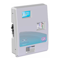
Fig. 14 – Lateral Panel
1 RJ45 plug
2 USB plug type “A”
3 Power IN RELE
4 Power IN Controller
5
PG7 Cable Glands for external
equipments
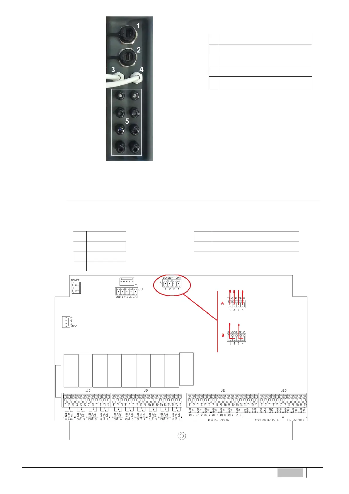
Connection Temperature Probe
For the connection of the temperature probe to remove the caps from the instrument (Fig. 1) and with a screwdriver,
the four locking screws. Then connect the probe to the terminal shown in Fig. 15 and indicated by J6.
(A) 4-wire probe (PT100) (B) 2-wire probe (PT100)
1 RED
1-2 Jumpered – BLACK (BLUE)
2 BLUE
3-4 Jumpered – RED (BROWN)
3 YELLOW
4 GREEN
Fig. 2 – Connector temperature sensor
ENGLISH
57