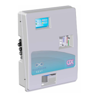
1 Presa RJ45
2 Ingresso USB plug type “A”
3 Alimentazione RELE’
4 Alimentazione Controller
5
Gruppo di passacavi PG7 per il
cablaggio delle apparecchiature
controllate (pompe, elettrovalvole,
Fig. 14 – Pannello laterale
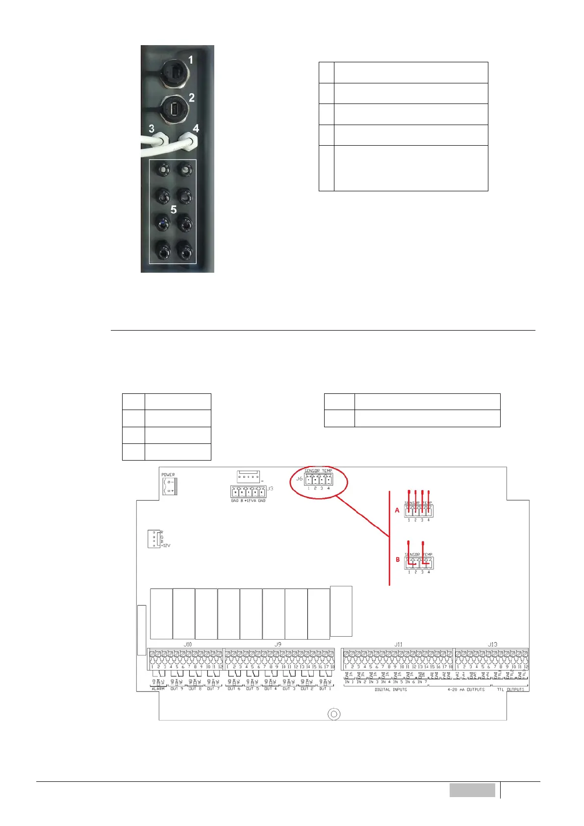
Collegamento Sonda di Temperatura
Per il collegamento della sonda di temperatura rimuovere i cappucci di protezione dello strumento (Fig. 1) e con
un giravite agire sulle quattro viti di chiusura. Collegare quindi la sonda al morsetto evidenziato in Fig. 15 e indicato
con J6.
(A) Sonda a 4 fili (PT100) (B) Sonda a 2 fili (PT100)
1 ROSSO
1-2 Ponticellare – NERO (BLU)
2 BLU
3-4 Ponticellare – ROSSO (MARRONE)
3 GIALLO
4 VERDE
Fig. 15 – Connettore sensore di temperatura
ITALIANO
93