Chapter 9 - Electrical
281
• If there is continuity through the circuit when
the transfer case is in gear the problem must
be identified and repaired to prevent the engine
from being started when the vehicle is in gear.
See Figure 9.10.
• To identify the switch that is failing to break the
circuit when the vehicle is in gear, engage the
gears one at a time.
• If the continuity does not change when “L” is
selected, then the problem is in the switch that is
mounted closer to the top of the transfer case.
• If the continuity does not change when “H” or “R”
is selected, then the problem is in the switch that
is mounted closer to the bottom of the transfer
case.
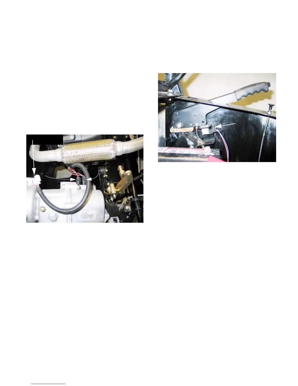
Figure 9.10
Lower switch
(F and H)
Upper switch
(L range)
Ohm test here
9c. The brake switch is not tied to the starter
circuit. It illuminates an LED on the hour
meter when the brake is engaged, and
sounds a warning beeper if the vehicle is
put in gear while the brake is engaged.
See Figure 9.11.
• The brake switch is located directly under the
parking brake handle, and it is easily accessible
by removing the parcel bin from beneath the
drivers seat.
It is a Normally Closed switch. When the brake
lever is pulled-up, the plunger extends and the
contacts close.
• An orange wire supplies power when the key
switch is in any position other than “STOP”.
• A blue wire with white trace carries power from
the switch directly to the hour meter and to the
common spade on the park buzzer relay.
Figure 9.11
Brake
Switch
 Loading...