Chapter 4 - Front Suspension and steering
137
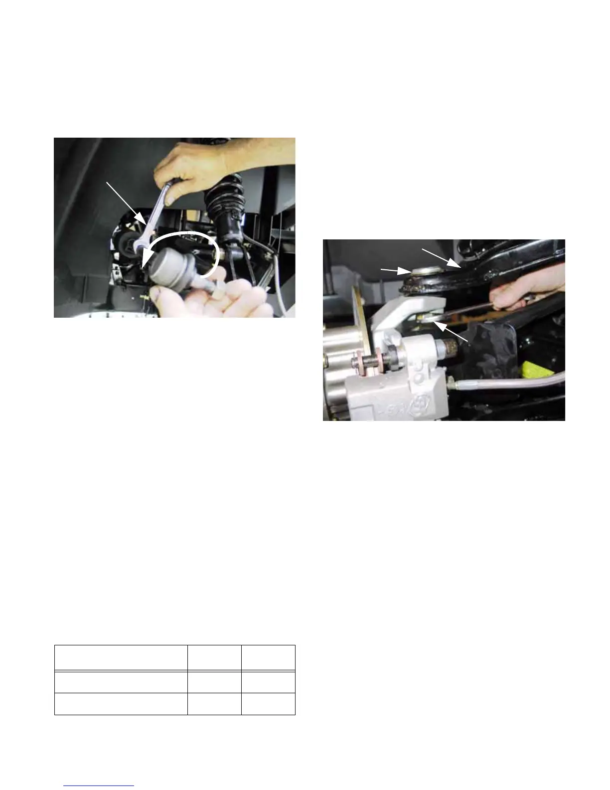
7. Once released from the steering arm on the hub
assembly, spin the tie rod end out of the tie rod.
A 9/16” wrench may be used on the square sec-
tion of the tie rod, to keep it from rotating.
See Figure 4.29.
8. If a new tie rod end is to be installed, measure
the position of the jam nut, and transfer it to the
new tie rod end.
• This will minimize the chance that replacing the
tie rod end will disturb the toe angle adjustment.
9. Install the new tie rod end to the same depth in
the tie rod as the old one was.
10. Insert the stud of the tie rod into the tapered bore
in the steering arm, and secure it with a self-
locking nut.
• If the locking feature of the nut has worn, replace
the nut with a new M12 x 1.25 nylon ring locking
nut. Threadlocking compound is not recom-
mended.
• Tighten the nut to a torque of 22-28 ft-lb. (30-38
Nm) using a 19mm wrench.
11. Install the wheel, and tighten the lug nuts to a
torque of 75 ft-lbs (102 Nm).
12. Check alignment, and test drive the vehicle in a
safe area before returning it to service.
Item ft-lbs N-m
Tie rod end stud nuts 42-64 60-88
Lug nuts 65-75 88-102
Figure 4.29
9/16” wrench
to hold tie rod
Loosen tie
rod end
Upper Ball Joint
Refer to the INSPECTION section of this chapter
for information on when to replace ball joints.
1. Lift and safely support the vehicle as described
in the INTRODUCTION section of this manual.
The vehicle should be supported by the frame.
2. Remove the front wheel using a 3/4” wrench.
3. Support the lower control arm with a jackstand.
4. Loosen the nut that holds the upper ball joint to
the front hub as far as possible using a 19mm
wrench. See Figure 4.30.
NOTE: When loosening nuts with nylon locking
rings that are installed on taper fit studs, loosen
the nut far enough to disengage the locking fea-
ture before separating the tapered joint. Other-
wise, the stud may rotate, making removal of the
nut difficult.
Figure 4.30
Upper control arm
Ball joint
Nut on upper
ball joint stud
 Loading...