Chapter 4 - Front Suspension and steering
138
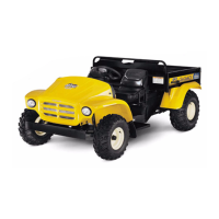
5. Separate the upper ball joint from the upper con-
trol arm: See Figure 4.31.
5a. Position a chisel as a wedge between the
top surface of the hub assembly and the
bottom surface of the upper control arm.
The chisel tip should not point toward the
joint.
5b. Drive the chisel in between the hub and
the upper control arm using a heavy ham-
mer.
5c. When there is sufficient clearance, remove
the nut from the ball joint stud. At this
point the arm and the hub should be sep-
arated.
6. Release the snap ring that holds the ball joint
into the upper control arm. See Figure 4.32.
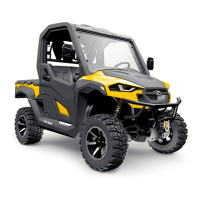
7. Position a two-jaw puller to drive the ball joint
downward, out of the upper control arm.
See Figure 4.33.
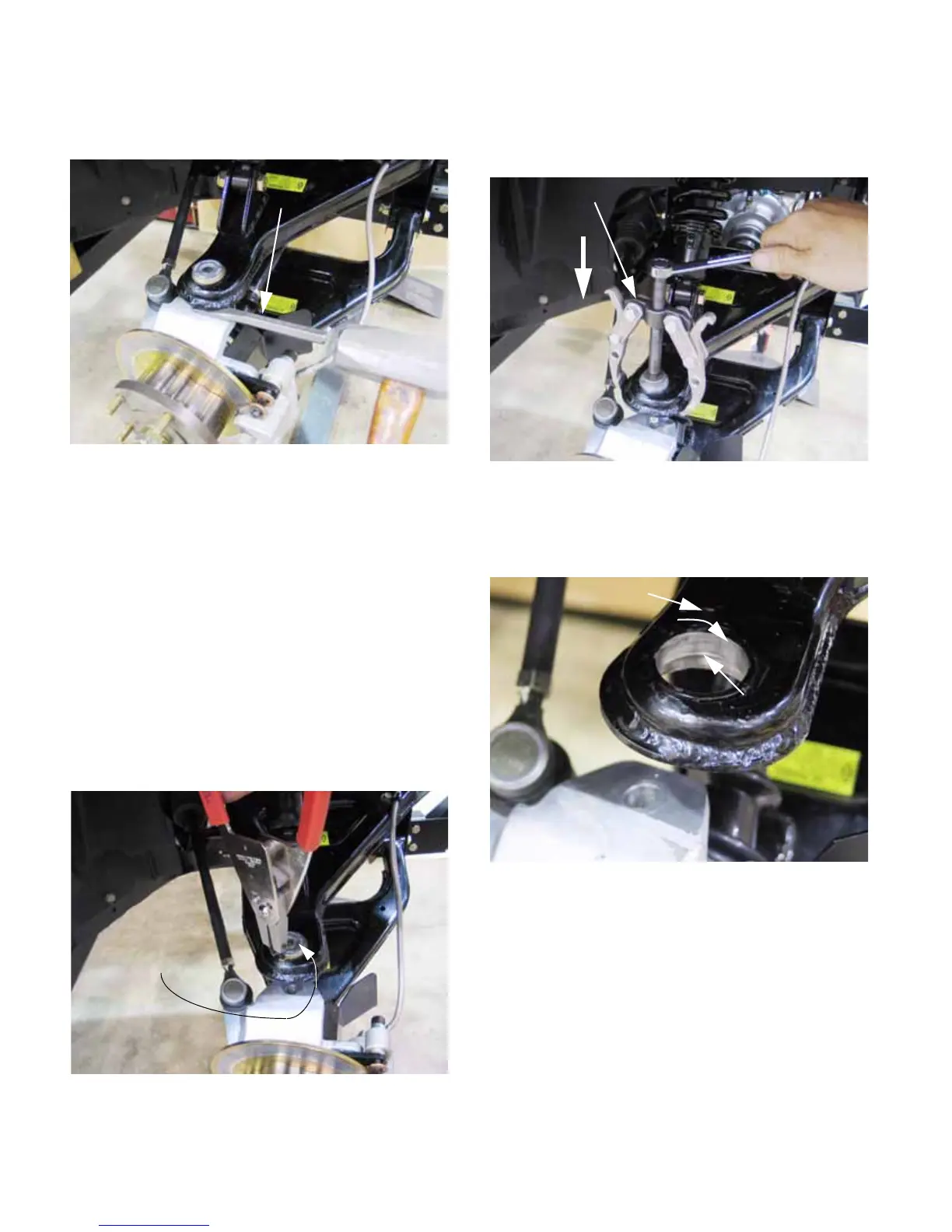
8. Clean, inspect, and lubricate the shouldered
bore in the upper control arm before installing
the new ball joint. See Figure 4.34.
9. Disconnect the bottom of the spring and damper
unit from the upper control arm using a pair of 3/
4” wrenches. Loosen the nut and bolt that hold
the top of the spring and damper unit to the
frame (1 turn).
10. Swing the spring and damper unit out of the way,
and turn the steering wheel to fully extend the tie
rod on the side being repaired. This will provide
the maximum range of available motion.
Figure 4.31
Chisel
Figure 4.32
Remove the
retaining ring
Upper ball joint
Figure 4.33
Two-jaw puller
Drive ball
joint down
Figure 4.34
Upper control arm
Ball joint bore
Step (shoulder)
 Loading...