Chapter 4 - Front Suspension and steering
134
Steering travel stop bolts
In normal service, these should not need adjusting. If it
is necessary to adjust the stop bolts, use the following
guidelines.
The stop bolts should be adjusted so that the maximum
outside angle of the constant velocity joint is 43º.
This angle can be checked precisely, with some diffi-
culty, using two straight-edges and a protractor.
In the field, a simpler method can be used:
1. Check or adjust the toe angle before making this
adjustment.
2. Using the string method described in the toe-
angle adjustment section of this chapter, confirm
that the steering is at the center of its travel.
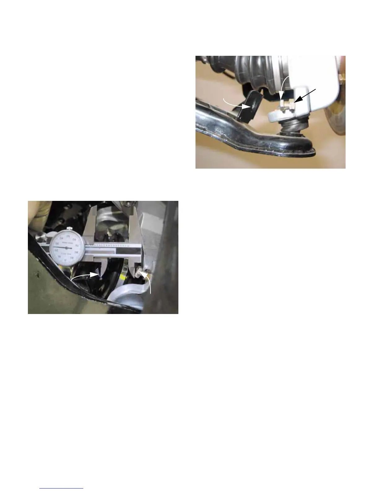
3. Measure the distance between the head of the
travel stop bolt and the point where it meets the
lower control arm. See Figure 4.21.
• The distance should be equal for both sides of
the front suspension.
• There should be 1.425” (3.62cm) between the
two points.
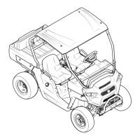
4. If adjustment is necessary: See Figure 4.22.
4a. Loosen the jam nut using a 7/16” wrench
4b. Thread the bolt in or out of the hub assem-
bly to achieve the correct adjustment.
4c. Secure the adjustment by tightening the
jam nut.
Figure 4.21
Travel stop bolt
contact point on bracket
on lower control arm
Figure 4.22
Travel stop bolt
Jam nut
Contact point
on bracket on
lower control arm
 Loading...