Chapter 9 - Electrical
312
11. Testing switches:
• Refer to the “COMPONENTS” section of this
chapter that describes the function of the individ-
ual switches to be tested.
• Switches can be tested “hot” by looking for volt-
age at the appropriate posts.
This is not definitive, since the source of the volt-
age is not always confirmed.
Checking for voltage does not work on switches
that work by providing a ground path to the mag-
neto primary windings or a solid state control
device.
• The most valid way to test switches is a conti-
nuity test.
11a. Understand the internal functions of the
switch. Key switches and PTO switches
can be fairly complex.
11b. Isolate the switch from the rest of the cir-
cuit.
11c. Test each pair of terminals for continuity in
all modes of switch operation: at-rest, and
actuated.
11d. Many switches on Cub Cadet equipment
are typed by their at-rest state: Normally
Open, Normally Closed, Common.
• Normally Open (N.O.) contacts do not complete
a circuit when the switch is at-rest (plunger
extended). They close to complete a path
through the switch when the plunger is
depressed.
• Normally Closed (N.C.) contacts complete a cir-
cuit when the switch is at-rest (plunger
extended). They open to break the path through
the switch when the plunger is depressed.
• Some Cub cadet switches contain more than
one pair of contacts. The same switch housing
can contain normally open and normally closed
switch elements.
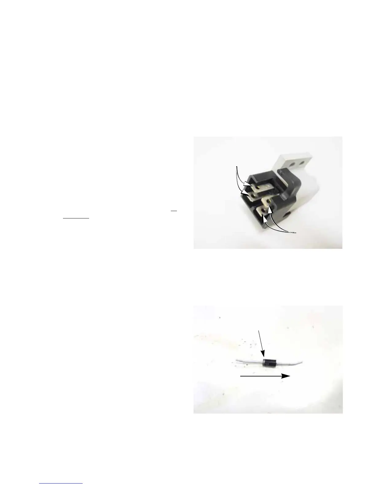
• When testing a switch that contains more than
one set of contacts (elements), the male spade
terminals associated with Normally Closed con-
tacts will be stamped “N.C.”
• The male spade terminals that are associated
with each-other face each-other broad-surface
to broad surface. See Figure 9.75.
12. Diodes
• What is a diode?: A diode acts like a one way
valve, allowing current to flow in only one direc-
tion. See Figure 9.76.
Figure 9.75
Normally Closed
switch element:
Spades marked: “NC”
Normally Open
switch element:
Spades blank
Figure 9.76
Silver band
(-)
(+)
electrons flow from the negative to the positive.
 Loading...