ELECTRICAL SYSTEM
113
Increased resistance
• Increased resistance is, as the name implies, an
increase in resistance.
• Causes: This can be caused by loose or cor-
roded connections, or connections that are insu-
lated by grease, paint, or coatings. Fasteners
finished in oil/phosphate or black oxide are bad
conductors. Use bright fasteners (zinc coated).
• Resistance can be a problem on the ground side
as well as the hot side of a system: remember
that electricity must complete a loop (circuit)
back the battery post. Any resistance in that loop
will interfere with the flow.
• Arguably the most common electrical failure,
and the hardest to find, increased resistance can
have more subtle symptoms than outright open
circuits. Many times effected circuits will still
partially function. It is not an open because
there is some current that can get through, but
the increase in resistance is enough to affect the
circuit.
The Tools
Equipment needed to diagnose an electrical system:
• DMM (Digital Multi-meter)
• Wiring schematic or diagram
Equipment that may be useful:
• Fused jumper wires.
• Test light (high impedance)
• Ammeter
• Battery charger
• Battery tester
• Battery jumper cables
• Hand tools to gain access to components.
• Flash light.
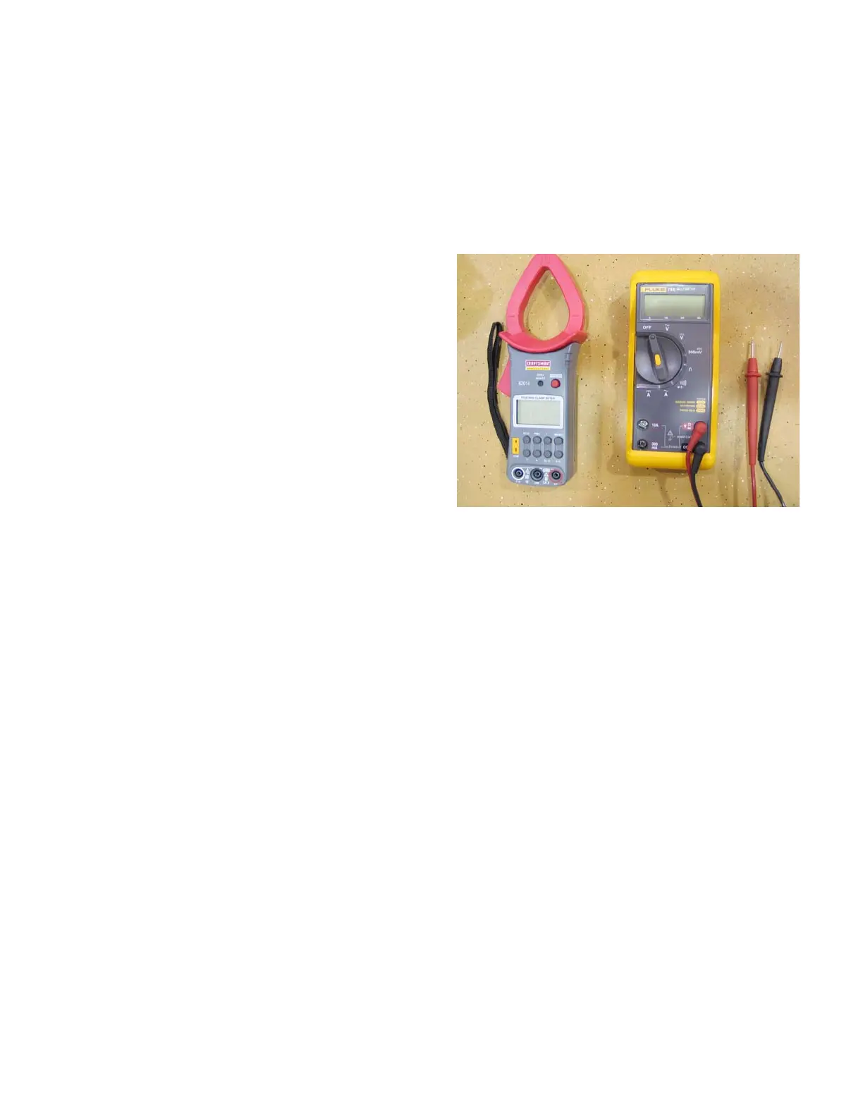
Digital Multi-meter
• A DMM is the most useful tool to trouble-shoot
any electrical system. There is an amazing vari-
ety of DMMs on the market. Some are very
basic, others are tailored to specific industries,
and some high-end graphing meters function
like oscilloscopes. Even the most basic ones are
quite versatile. See Figure 7.31.
Uses:
Voltage: Set meter to read “Volts DC ( _ _ _ )” if using
an auto-ranging meter or to an appropriate scale (typi-
cally 20 Volts DC) if using a more basic model.
• Connect the meter in parallel to the circuit
being measured, between the test point and a
known-good ground. Turn-on the circuit to be
tested, and read the meter. For most tests the
engine need not be running, but the key will be
turned-on.
• If there is question about which end of the circuit
the electricity is coming from, the circuit may be
disconnected near the test point.
• If the meter is connected with the polarity
reversed, a “-” will appear in front of the voltage
reading. It has no ill effects on the meter nor on
accuracy.
• If the meter is set to Volts AC (~) the reading will
be much lower that expected, but no physical
harm will be done to the meter nor the equip-
ment being diagnosed. It may waste some time
though.
Figure 7.31

 Loading...